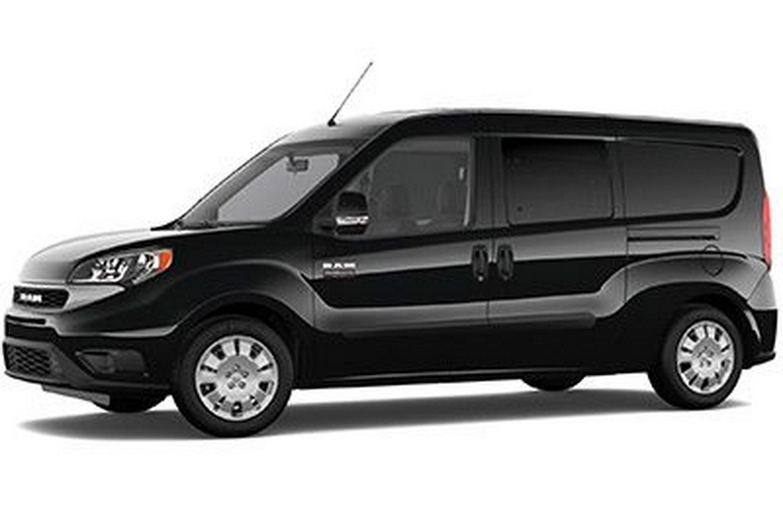
This article covers the Ram ProMaster City produced from 2019 to 2022. Here you will find the 2019, 2020, 2021 and 2022 Ram ProMaster City fuse box diagrams, information on the location of the fuse boxes in the vehicle and the assignment of each fuse (fuse layout).
Underhood Fuses
Fuse Box Location
The Front Distribution Unit is located on the right side of the engine compartment, next to the battery. To access the fuses, remove fasteners and remove the cover. The ID number of the electrical component corresponding to each fuse can be found on the back of the cover.
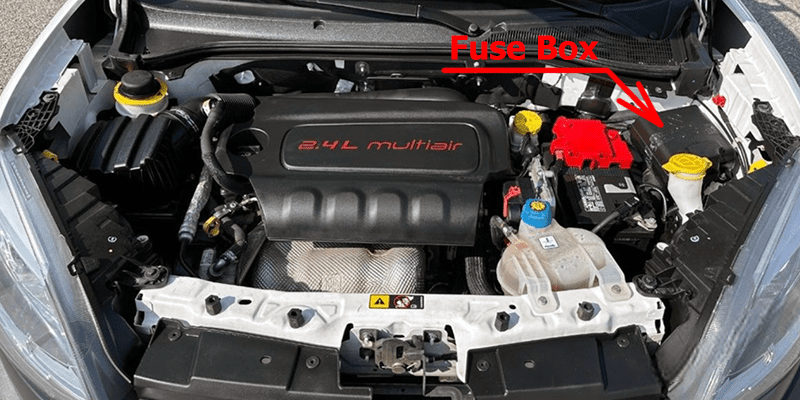
Fuse Box Diagram
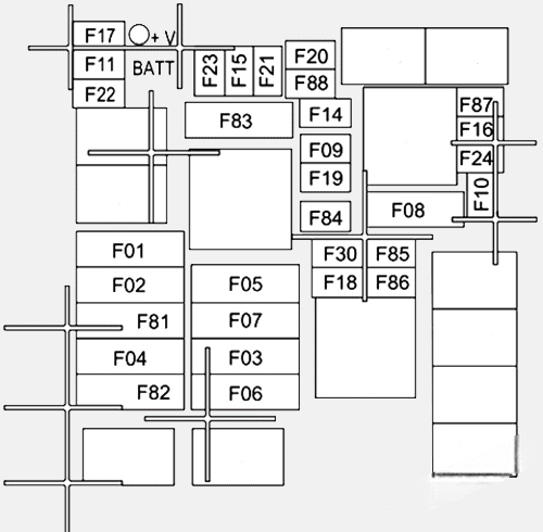
Assignment of the fuses in the engine compartment
| № | Maxi Fuse | Mini Fuse | Description |
|---|---|---|---|
| F01 | 60A Blue | – | Body Controller |
| F02 | 40A Orange | – | Rear Power Windows, Fog Lamps, Front Heated Seats |
| F02 | 30A Green | – | Rear Power Windows, Front Heated Seats, Fog Lamps |
| F02 | 20A Yellow | – | Front Heated Seats |
| F03 | 20A Yellow | – | Ignition Switch |
| F04 | 40A Orange | – | BSM System Module |
| F06 | 20A Yellow | – | Radiator Fan – Low Speed |
| F07 | 50A Red | – | Radiator Fan – High Speed |
| F08 | 40A Orange | – | Blower Motor |
| F09 | – | – | – |
| F10 | – | 15A Blue | Horn |
| F11 | – | 10A Red | Secondary Loads ECM |
| F14 | – | 15A Blue | High Beam |
| F15 | – | 15A Blue | 2019-2020: IP Power Outlet 12V |
| F16 | – | 5A Tan | ECM and Transmission Shifter |
| F17 | – | 25A Clear | ECM Power Loads |
| F18 | – | 5A Tan | ECM Load, Main Relay |
| F19 | – | 7.5A Brown | Air Conditioning |
| F20 | – | 30A Green | Rear Defroster |
| F21 | – | 5A Tan | Key Unlock |
| F22 | – | 10A Red | Primary ECM Loads |
| F23 | – | 20A Yellow | BSM System |
| F24 | – | 5A Tan | BSM System, Positive Key and Steering Angle Sensor |
| F30 | – | 15A Blue | 2nd Instrument Panel Power Outlet (Battery) |
| F83 | 20A Yellow | – | Fuel Pump |
| F84 | – | 15A Blue | AT Module |
| F85 | – | 15A Blue | Rear Power Outlet 12 Volts (ACC/ON/ RUN) |
| F86 | – | 15A Blue | 2020-2022: IP Power Outlet 12 Volts (ACC/ON/ RUN) |
| F87 | – | 5A Tan | IBS |
| F88 | – | 7.5A Brown | External Mirror Defrost |
Interior Fuses
Fuse Box Location
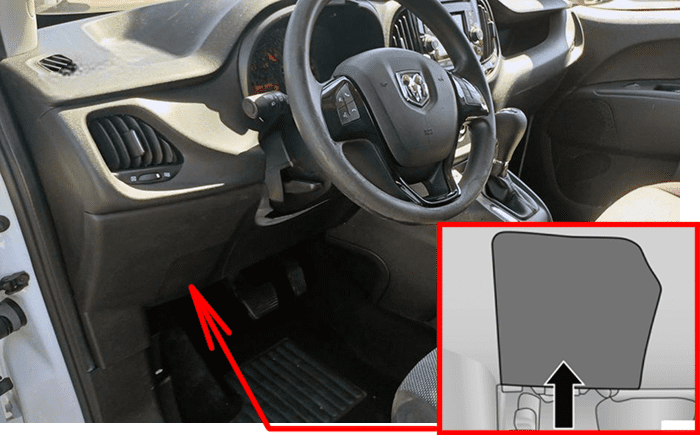
The interior fuse panel is part of the Body Control Module (BCM) and is located on the driver’s side under the instrument panel. Remove the cover to access. The central power fuse panel is located on the driver’s side under the instrument panel.
Fuse Box Diagrams
Body Control Module (BCM)
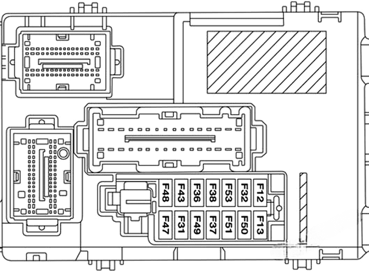
Assignment of the fuses in the Body Control Module
| № | Mini Fuse | Description |
|---|---|---|
| F53 | 5A Beige | KL 30 (+30) – IPC, FTM |
| F38 | 20A Yellow | Central Doors Locking |
| F36 | 15A Blue | KL 30 (+30) – TPMS, EOBD, HVAC, Radio, USB, SGW |
| F43 | 15A Blue | Bi-Directional Washer Pump |
| F48 | 20A Yellow | Passenger Power Windows |
| F13 | 7.5A Brown | 2022: Supply for left low beam bulb or discharge lamp |
| F50 | 7.5A Brown | KL 15 (+15) – Air-Bag |
| F51 | 7.5A Brown | KL 15 (+15) – External Mirror Adjustment Command, HVAC, RVC, HWB Coils |
| F37 | 5A Beige | KL 15 (+15) – Brake Pedal Switch (N.O.), IPC, Brake Pedal Switch (N.C.) |
| F49 | 5A Beige | KL 15 (+15) – PAM, CSS Lighting, TTM, SGW, Heaters Light, ECM Backlighting |
| F31 | 5A Beige | KL 15a (INT A) – HWB, MCO |
| F47 | 20A Yellow | Driver Power Windows |
Central Unit Fuse Panel
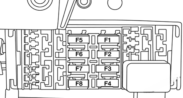
Assignment of the fuses in the Central Unit Fuse Panel
| № | Mini Fuse | Description |
|---|---|---|
| F1 | 10A Red | Front Heated Seat Passenger |
| F2 | 10A Red | Front Heated Seat Driver |
| F3 | 20A Yellow | Rear Power Window Driver side |
| F4 | 20A Yellow | Rear Power Window Passenger side |
| F5 | 15A Blue | Fog Lamps |
