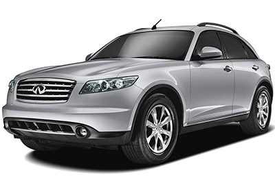
In this article, we look at the first-generation Infiniti FX (S50), which was produced from 2003 to 2008. You can find diagrams of the fuse box for the Infiniti FX35/FX45 for the years 2003, 2004, 2005, 2006, 2007 and 2008. You can also find information about where to find the fuse panels inside the car and about what each fuse and relay does.
The fuses for the cigar lighter (power outlet) in the Infiniti FX35/FX45 are fuses #2, #3, #4 and #7. You will find them in the passenger compartment fuse box.
Passenger Compartment Fuse Box
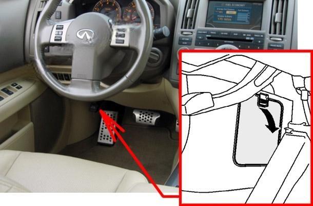
Fuse Box Location
The fuse box is located behind the cover under the instrument panel.
Fuse Box Diagram
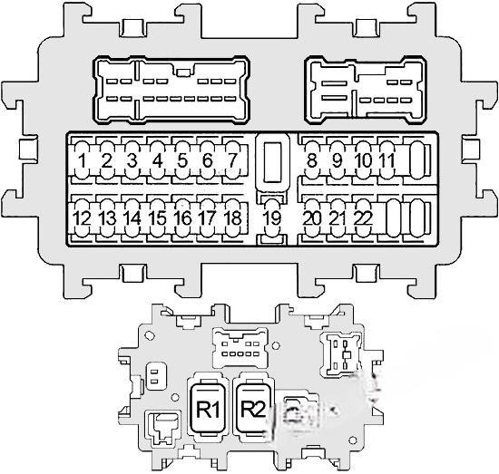
Assignment of fuses in the instrument panel
| № | Amper Rating | Description |
|---|---|---|
| 1 | 15 | Body Control Module (BCM), Engine Control Module (ECM), Fuel Injectors |
| 2 | 15 | Luggage Room Power Socket |
| 3 | 15 | Rear Power Socket |
| 4 | 15 | Front Power Socket #2 |
| 5 | – | Not Used |
| 6 | 10 | Audio, Display Control Unit, Satellite Radio Tuner, Unified Meter and A/C Amplifier, A/C and AV Switch, Antenna Amplifier, Body Control Module (BCM), Rear View Camera Control Unit, NAVI Control Unit, DVD Player, TEL Adapter Unit, Intelligent Key Unit, Outside Key Antenna, Combination Meter |
| 7 | 15 | Front Power Socket #1 |
| 8 | 15 | Heated Mirror |
| 9 | 10 | Combination Meter, Automatic Drive Positioner Control Unit |
| 10 | 15 | Blower Motor, Unified Meter and A/C Amplifier |
| 11 | 15 | Blower Motor, Unified Meter and A/C Amplifier |
| 12 | 10 | Intelligent Cruise Control (ICC), ICC Sensor, ICC Brake Switch, ICC Brake Hold Relay, Engine Control Module, Unified Meter and A/C Amplifier, Stop Lamp Switch, Shift Lock Solenoid, ECV Solenoid Valve (A/C Compressor), Display Control Unit, NAVI Control Unit, TEL Adapter Unit, Intelligent Key Unit, Steering Angle Sensor, Snow Mode Switch, Lane Departure Warning (LDW) Switch, LDW Camera Unit, LDW Chime, Auto Anti-Dazzling Inside Mirror (Compass), ASCD Brake Switch, Rear Window Defogger Relay, AWD Control Unit |
| 13 | 10 | Air Bag Diagnosis Sensor Unit, Occupant Classification System Control Unit |
| 14 | 10 | Combination Meter |
| 15 | 10 | Heated Seat Switch |
| 16 | 10 | 2003-2005: Oxygen Sensors, Air Fuel Ratio Sensors; 2006-2008: Not Used |
| 17 | 20 | BOSE Speaker Amplifier |
| 18 | 15 | Back Door Closure Control Unit |
| 19 | 10 | Combination Meter, Unified Meter and A/C Amplifier, Data Link Connector, Rear View Camera Control Unit, Security Indicator Lamp, Clock |
| 20 | 10 | Stop Lamp Switch, Intelligent Cruise Control (ICC), ICC Brake Hold Relay, ABS, Unified Meter and A/C Amplifier, Rear Combination Lamp Control Unit |
| 21 | 10 | AWD Control Unit |
| 22 | 15 | Body Control Module (BCM), Key Switch, Key Switch and Ignition Knob Switch, NATS Antenna Amplifier, Automatic Drive Positioner Control Unit |
| Relay | ||
| R1 | Blower | |
| R2 | Accessory |
Engine Compartment Fuse Boxes
Fuse Box Location
Two fuse blocks and relay block #1 are located next to the battery under the cover on the passenger side. To access some items, you need to remove some parts of the casing near the battery. From 2006 to 2008, under the cover on the driver’s side is the relay block #2.
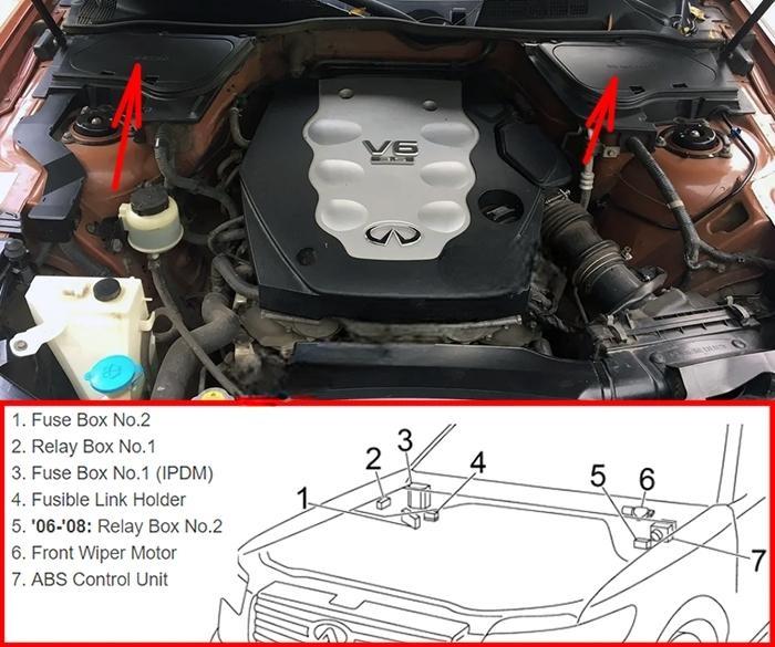
Fuse Box #1 Diagram
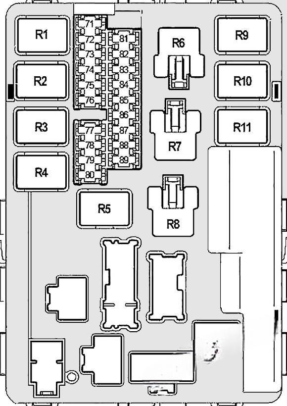
Assignment of fuses in the engine compartment fuse Box #1
| № | Amper Rating | Description |
|---|---|---|
| 71 | 10 | Tail Lamp Relay, Parking Lamp, Tail Lamp, Side Marker Lamp, IPDM CPU, Headlamp Aiming Control, Rear Combination Lamp Control Unit, License Plate Lamp, Glove Box Lamp, Combination Switch, Microphone (Illumination: A/T Device, Snow Mode Switch, VDC OFF Switch, Clock, Hazard Switch, Heated Seat Switch, Door Mirror Remote Control Switch, LDW Switch, A/C and AV Switch, DVD Player, Front Power Socket) |
| 72 | 10 | Right Headlamp (High Beam) |
| 73 | 30 | Front Wiper Relay |
| 74 | 10 | Left Headlamp (High Beam) |
| 75 | 20 | Rear Window Defogger Relay |
| 76 | 15 | Right Headlamp (Low Beam) |
| 77 | 20 | Engine Control Module (ECM), ECM Relay, Intake Valve Timing Control Solenoid Valve, Mass Air Flow Sensor, Crankshaft Position Sensor, Camshaft Position Sensors, EVAP Canister Purge Volume Control Solenoid Valve, Ignition Coils, Condenser, Intake Valve Timing Control Position Sensors (VK45DE) |
| 78 | 15 | IPDM CPU, Windshield Wiper De-icer |
| 79 | 10 | Air Conditioner Compressor Clutch |
| 80 | 20 | Rear Window Defogger Relay, Fuse: “8” |
| 81 | 15 | Fuel Pump Relay, Fuel Level Sensor Unit and Fuel Pump, Engine Control Module (ECM) |
| 82 | 10 | ABS |
| 83 | 10 | Transmission Control Module (TCM), Back-Up Lamp Relay, Display Control Unit, NAVI Control Unit, Rear View Camera Control Unit |
| 84 | 10 | Combination Switch, Front and Rear Washer System |
| 85 | 10 | Air Fuel Ratio Sensors, Heated Oxygen Sensors |
| 86 | 15 | Left Headlamp (Low Beam) |
| 87 | 15 | Throttle Control Motor Relay, Engine Control Module (ECM) |
| 88 | 15 | Front Fog Lamp Relay |
| 89 | 10 | Data Link Connector, EVAP Canister Vent Control Valve, VIAS Control Solenoid Valve (VK45DE) |
| Relay | ||
| R1 | Engine Control Module | |
| R2 | Headlamp High | |
| R3 | Headlamp Low | |
| R4 | Starter | |
| R5 | Ignition | |
| R6 | Cooling Fan (№3) | |
| R7 | Cooling Fan (№1) | |
| R8 | Cooling Fan (№2) | |
| R9 | Throttle Control Motor | |
| R10 | Fuel Pump | |
| R11 | Front Fog Lamp |
Fuse Box #2 Diagram

Assignment of fuses in the engine compartment fuse Box #2
| № | Amper Rating | Description |
|---|---|---|
| 31 | 30 | Trailer Tow Lights |
| 32 | 15 | Audio, Subwoofer, Display Control Unit, A/C and AV Switch, NAVI Control Unit, DVD Player, TEL Adapter Unit |
| 33 | 10 | Alternator |
| 34 | 15 | Horn Relay |
| 35 | 10 | Intelligent Cruise Control (ICC) |
| 36 | 10 | Daytime Light Relay |
| 37 | 10 | Transmission Control Module (TCM) |
| 38 | 10 | Intelligent Key Unit, Key Switch and Ignition Knob Switch, Passenger Side Select Unlock Relay, Steering Lock Unit, Intelligent Key Warning Buzzer |
| F | 40 | Ignition Switch, Starter Relay |
| G | 40 | Cooling Fan Relay №1, Cooling Fan Relay No.3 |
| H | 40 | Cooling Fan Relay №2 |
| I | 50 | ABS |
| J | – | Not Used |
| K | 30 | Accessory Relay No.2 (Fuses: “2”, “3”) |
| L | 30 | ABS |
| M | 50 | Body Control Module (BCM), Automatic Drive Positioner Control Unit, Power Seat, Power Window, Sunroof, Rear Wiper, Interior Lighting, Turn Signal Lights, Hazard |
| Relay | ||
| R1 | Horn | |
| R2 | Accessory №2 |
Fusible Link Block
The main fuses are located on the positive terminal of the battery.
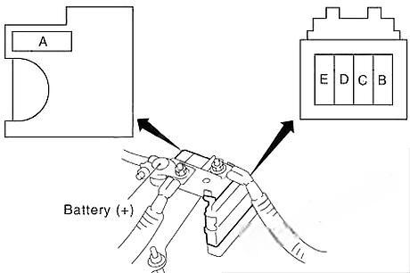
| № | Amper Rating | Description |
|---|---|---|
| A | 120 | Alternator, Fuse: “B”, “C” |
| B | 100 | Fuses: “32”, “33”, “34”, “35”, “36”, “37”, “38”, “F”, “G”, “H”, “I”, “K”, “L”, “M” |
| C | 80 | Headlamp High Relay (Fuses: “72”, “74”), Headlamp Low Relay (Fuses: “76”, “86”), Fuses: “71”, “73”, “75”, “87”, “88” |
| D | 60 | Accessory Relay (Fuses: “4”, “6”, “7”), Blower Relay (Fuses: “10”, “11”), Fuses: “17”, “18”, “19”, “20”, “21”, “22” |
| E | 80 | Ignition Relay (Air Conditioner Relay, Front Wiper Relay, Front Wiper High Relay, Fuses: “81”, “82”, “83”, “84”, “85”, “89”), Fuses: “77”, “78”, “79”, “80” |
Relay Box #1
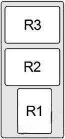
| № | Relay |
|---|---|
| R1 | Daytime Light |
| R2 | ICC Brake Hold |
| R3 | Rear Window Defogger |
Relay Box #2

| № | Relay |
|---|---|
| R1 | Back-Up Lamp |
| R2 | Not Used |
