generated by pixel @ 2022 06 23t03:10:43.412188
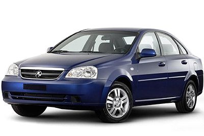
The Holden Viva (JF) compact car was manufactured from 2004 to 2008. In this article you will find the fuse box diagrams for the Holden Viva 2005, 2006, 2007 and 2008, as well as information on the location of the fuse boxes in the vehicle and the assignment of each fuse (fuse layout) and relay.
The fuses are located on the driver’s side wall of the instrument panel.
To open the fuse cover in the dash panel, open the driver’s side door, pull the top of the cover out.
Fuse Box Diagram
Assignment of the fuses in the dashboard
| № | Amps | Circuits protected |
|---|---|---|
| 1 | 10A | Airbag |
| 2 | 10A | Electronic control module |
| 3 | 15A | Turn signal |
| 4 | 15A | Cluster |
| 5 | 10A | Engine |
| 6 | 20A | Heating and air conditioning system |
| 7 | 15A | Sunroof (if equipped) |
| 8 | 20A | Wiper |
| 9 | 10A | Anti-lock brake system (if equipped) |
| 10 | 10A | Immobiliser |
| 11 | 10A | Traction control module (if equipped) |
| 12 | 15A | Hazard flashers |
| 13 | 15A | Anti-theft system (if equipped) |
| 14 | 10A | Diagnosis |
| 15 | 10A | Sound system; clock |
| 16 | 15A | Extra jack (if equipped) |
| 17 | 15A | Lighter |
| 18 | 10A | Backup lamps |
| 19 | 15A | Rear fog lamps (if equipped) |
| 20 | 15A | Automatic climate control (if equipped); clock |
| 21 | 15A | Sound system |
| 22 | 10A | Immobiliser (if equipped) |
This fuse box is located on the passenger side of the engine compartment, it contains circuit fuses, main fuses and relays.
To remove the cover, press the catch on the side of the fuse box towards the engine and release the two tabs at the opposite side.
Fuse Box Diagram
Assignment of the fuses in the engine compartment
| № | Amps | Circuits protected |
|---|---|---|
| 1 | 30A | Main battery |
| 2 | 60A | Anti-lock brake system (if equipped) |
| 3 | 30A | Blower motor |
| 4 | 30A | Ignition 2 |
| 5 | 30A | Ignition 1 |
| 6 | 25A | Headlamp |
| 7 | 10A | Electronic control module |
| 8 | 10A | Anti-lock brake system warning light module |
| 9 | 15A | Interior fuse block |
| 10 | 15A | Fuel pump |
| 11 | 10A | Air conditioning system |
| 12 | 15A | Horn |
| 13 | 15A | High beam headlamp |
| 14 | 20A | Driver’s power windows |
| 15 | 15A | Stop lamps |
| 16 | 15A | Door locks |
| 17 | 10A | Heated mirror |
| 18 | 15A | Fog lamp (if equipped) |
| 19 | 10A | Left illumination |
| 20 | 15A | Injector |
| 21 | 15A | Engine management system |
| 22 | 10A | Left low beam headlamp |
| 23 | 10A | Left low beam headlamp |
| 24 | 20A | Low speed electric fan |
| 25 | 30A | Demister |
| 26 | 30A | High speed electric fan |
| 27 | 20A | Power windows |
| 28 | 10A | Right illumination |
| 29 | 10A | Right low beam headlamp |
| Relays | ||
| 30 | Low speed electric fan | |
| 31 | Demister | |
| 32 | High speed electric fan | |
| 33 | Front fog lamp (if equipped) | |
| 34 | Air conditioning compressor | |
| 35 | Fuel pump | |
| 36 | Power windows | |
| 37 | Illumination | |
| 38 | Horn | |
| 39 | Main | |
| 40 | Headlamp |