
In this article we take a look at the first-generation Holden Trax (TJ, facelift) produced from 2017 to 2020. Here you will find the fuse box diagrams for the 2017, 2018, 2019 and 2020 Holden Trax, get information on the location of the fuse boxes inside the car and learn about the assignment of each fuse (fuse layout) and relay.
Passenger Compartment Fuse Box
Fuse Box Location
The interior fuse block is located in the glove box.
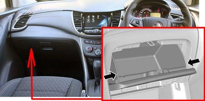
- Open the glove box.
- Squeeze the top outer edges of the glove box towards the centre and lower downwards.
- Release the damper on the left side of the glovebox.
Fuse Box Diagram
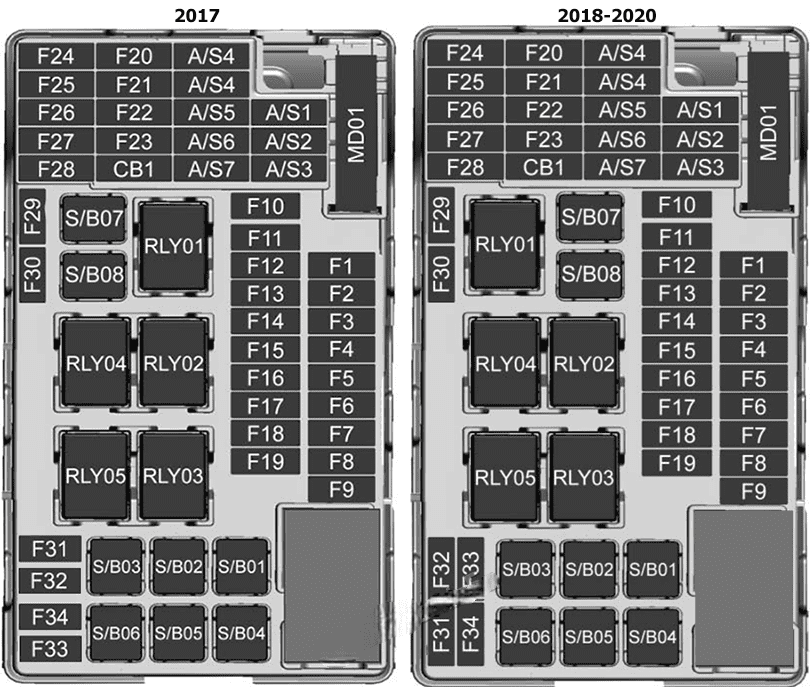
Assignment of the fuses in the dashboard
| № | Description |
|---|---|
| F1 | BCM 1 |
| F2 | BCM 2 |
| F3 | BCM 3 |
| F4 | BCM 4 |
| F5 | BCM 5 |
| F6 | BCM 6 |
| F7 | BCM 7 |
| F8 | BCM 8 |
| F9 | DLIS |
| F10 | SDM B+ |
| F11 | DLC |
| F12 | HVAC MDL |
| F13 | L/GATE RLY |
| F14 | CGM |
| F15 | 2018-2020: LDW Gentex |
| F16 | – |
| F17 | ESCL B+ |
| F18 | 2017: UPA B+ / SBZA BT 2018-2020: PAS / SBZA |
| F19 | BCM RVC |
| F20 | Clock Spring |
| F21 | 2017: AC APO 2018-2020: APO AC / PRNDL |
| F22 | 2017: DC APO 2018-2020: APO DC FRT |
| F23 | – |
| F24 | – |
| F25 | 2018: OnStar |
| F26 | 2018: EVP |
| F27 | 2017: IPC 2018-2020: IPC PTC RLAD |
| F28 | 2018-2020: TRLR Feed2 |
| F29 | – |
| F30 | – |
| F31 | IPC B+ |
| F32 | Audio / Nav |
| F33 | 2018-2020: TRLR Feed1 |
| F34 | PEPS Module |
| S/B01 | 2018-2020: PTC 1 |
| S/B02 | 2018-2020: PTC 2 |
| S/B03 | PWR WNDW MTR FRT |
| S/B04 | PWR WNDW REAR |
| S/B05 | Logistic Mode RLY |
| S/B06 | 2018-2020: PWR Seat DR |
| S/B07 | – |
| S/B08 | Trailer Interface Module |
| Relays | |
| RLY1 | ACC/RAP |
| RLY2 | L/GATE |
| RLY3 | – |
| RLY4 | Blower |
| RLY5 | Logistic Mode |
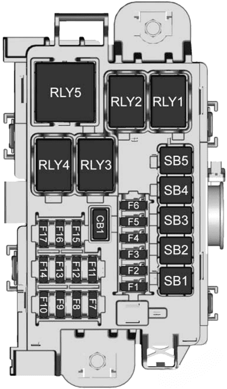
Engine Compartment Fuse Box
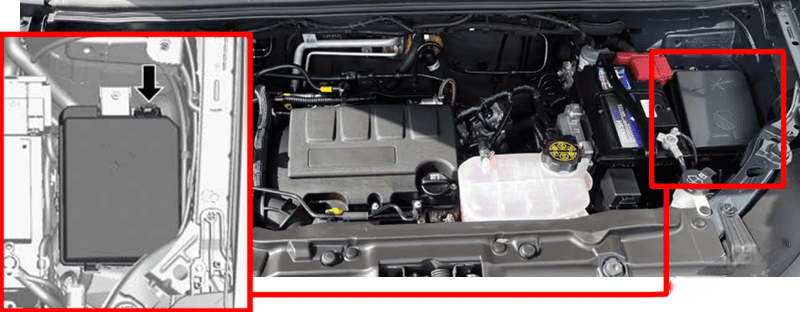
Fuse Box Location
To disengage the cover, lift upwards and remove.
Fuse Box Diagram
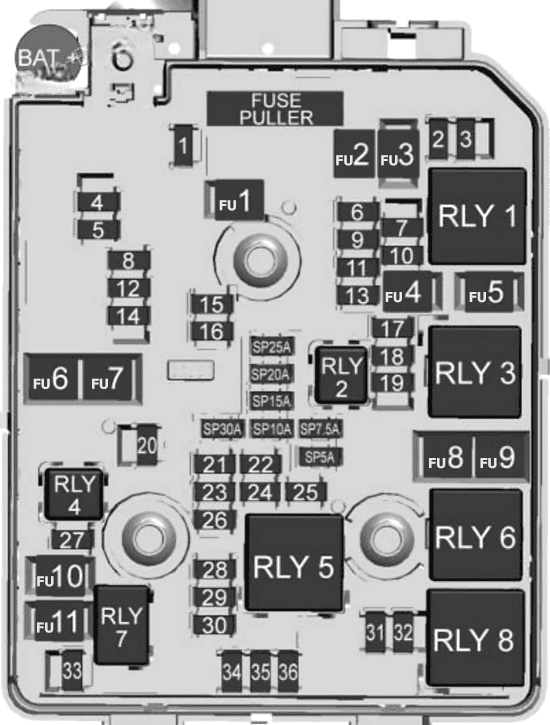
Assignment of the fuses in the engine compartment
| № | Description |
|---|---|
| F1 | Sunroof |
| F2 | OSRVM SW, Rain Sensor, PWR Window Driver |
| F3 | – |
| F4 | – |
| F5 | EBCM Valve |
| F6 | – |
| F7 | ESCL |
| F8 | TCM B+ |
| F9 | – |
| F10 | HDLP Leveling SW, HDLP Leveling MTR LH/RH, Rear Vision Camera ISRVM |
| F11 | Rear Wiper |
| F12 | RR WDW Defog |
| F13 | – |
| F14 | OSRVM Heat |
| F15 | – |
| F16 | Heated Seat Module |
| F17 | 2017: Compass Module, TIM R/C 2018: Compass Module, TIM DC/DC Converter FSCM R/C 2019-2020: TIM |
| F18 | ECM R/C, TCM R/C, FICM R/C |
| F19 | Fuel Pump |
| F20 | – |
| F21 | Fan RLY (AUX BEC) |
| F22 | – |
| F23 | Ignition Coil, Injector Coil |
| F24 | Washer Pump |
| F25 | – |
| F26 | 2017: Canister Purge SOL, Water Valve SOL, Turbo Wastegate SOL, Turbo Bypass SOL, O2 Sensor Pre/Post 2018-2020: EMS Var-1 |
| F27 | – |
| F28 | – |
| F29 | ECM PT IGN-1, IGN-2 |
| F30 | 2017: MAF Sensor 2018-2020: EMS Var-2 |
| F31 | High Beam LH |
| F32 | High Beam RH |
| F33 | ECM B+ |
| F34 | Horn |
| F35 | A/C Clutch |
| F36 | Front Fog Lamp |
| FU1 | EBCM Pump |
| FU2 | FRT Wiper |
| FU3 | Blower |
| FU4 | IEC R/C |
| FU5 | – |
| FU6 | – |
| FU7 | – |
| FU8 | Cooling Fan Low/Mid |
| FU9 | Cooling Fan High |
| FU10 | EVP |
| FU11 | Starter SOL |
| SP | Spare Fuses |
| Relays | |
| 1 | Run Crank |
| 2 | Fuel Pump |
| 3 | 2018-2020: Cooling Fan Mid |
| 4 | – |
| 5 | PT Relay |
| 6 | Cooling Fan High |
| 7 | Starter |
| 8 | Cooling Fan Low |
Auxiliary relay box
To disengage the cover, lift upwards and remove.
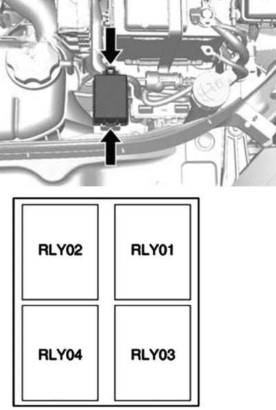
| № | Relays |
|---|---|
| RLY01 | ELECTRIC VACUUM PUMP |
| RLY02 | COOLING FAN 1 |
| RLY03 | COOLING FAN 2 |
| RLY04 | – |
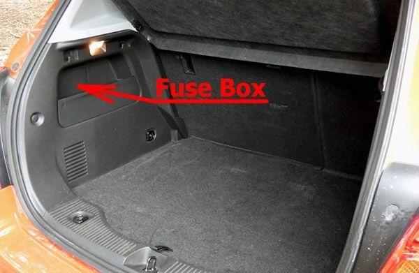
Luggage Compartment Fuse Box
Fuse Box Location
The rear compartment fuse box is located in the passenger side of the rear compartment. To remove the cover, pull outwards.
Fuse Box Diagram (2017)
Assignment of the fuses in the trunk (2017)
| № | Description |
|---|---|
| F1 | – |
| F2 | – |
| F3 | – |
| F4 | – |
| F5 | – |
| F6 | – |
| F7 | – |
| F8 | – |
| F9 | – |
| F10 | – |
| F11 | – |
| F12 | – |
| F13 | – |
| F14 | – |
| F15 | – |
| F16 | – |
| F17 | Spare |
| F18 | – |
| S/B01 | – |
| S/B02 | – |
| S/B03 | – |
| S/B04 | AC DC INV |
| S/B05 | – |
| S/B06 | – |
| S/B07 | – |
| S/B08 | – |
| Relays | |
| RLY1 | – |
| RLY2 | – |
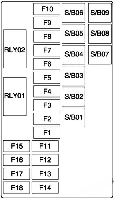
Fuse Box Diagram (2018-2020)
Assignment of the fuses in the trunk (2018-2020)
| № | Description |
|---|---|
| F1 | 2018: Amplifier |
| F2 | 2018: RDCM |
| F3 | – |
| F4 | 2018: NOX Soot |
| F5 | 2018: NOX Soot/Heater Pipe |
| F6 | 2018: SCRPM |
| F7 | 2018: SCRPM |
| F8 | – |
| F9 | – |
| F10 | – |
| F11 | – |
| F12 | – |
| F13 | – |
| F14 | – |
| F15 | – |
| F16 | – |
| F17 | – |
| SB1 | 2018: DC/DC |
| SB2 | 2018: DC/DC |
| SB3 | DC/AC Inverter |
| SB4 | 2018: NOX Heater Pipe |
| SB5 | – |
| Relays | |
| RLY1 | – |
| RLY2 | – |
| RLY3 | 2018: ECM/NOX Soot |
| RLY4 | 2018: ECM/NOX Heater Pipe |
| RLY5 | – |