
This article covers the first generation Holden Trax (TJ, pre-facelift) produced from 2013 to 2016. Here you will find the fuse box diagrams for the 2013, 2014, 2015 and 2016 Holden Trax, get information on the location of the fuse boxes inside the car and learn about the assignment of each fuse (fuse layout) and relay.
Passenger Compartment Fuse Box
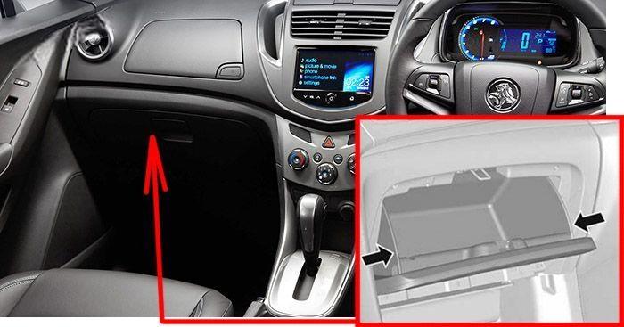
Fuse Box Location
The interior fuse block is located in the glove box. Squeeze the top outer edges of the glove box towards the centre and lower downwards.
Fuse Box Diagram
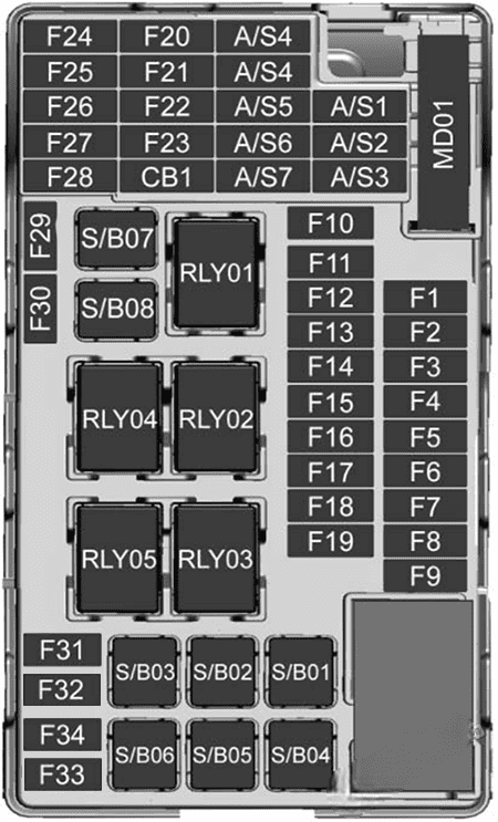
Assignment of the fuses in the dashboard
| № | Amps | Description |
|---|---|---|
| F1 | 15A | BCM 1 |
| F2 | 15A | BCM 2 |
| F3 | 15A | BCM 3 |
| F4 | 15A | BCM 4 |
| F5 | 15A | BCM 5 |
| F6 | 15A | BCM 6 |
| F7 | 15A | BCM 7 |
| F8 | 30A | BCM 8 |
| F9 | 2A | DLIS |
| F10 | 10A | SDM B+ |
| F11 | 7.5A | DLC |
| F12 | 10A | HVAC MDL |
| F13 | 10A | L/GATE RLY |
| F14 | 10A | UPA MDL |
| F15 | – | – |
| F16 | – | – |
| F17 | – | – |
| F18 | 5A | 2015-2016: RAIN SNSR |
| F19 | 5A | BCM RVC |
| F20 | 2A | SWC BKLT |
| F21 | 10A | AC APO |
| F22 | 20A | DC APO |
| F23 | – | – |
| F24 | – | – |
| F25 | – | – |
| F26 | 10A | 2013-2014: SDM RC/AOS DISPLAY |
| F27 | 10A | IPC / CMPS MDL |
| F28 | 10A | HDLP SW / DC CVT / CLTCH SW |
| F29 | – | – |
| F30 | – | – |
| F31 | 5A | IPC B+ |
| F32 | 15A | RDO/CHIME |
| F33 | – | – |
| F34 | – | – |
| S/B01 | – | – |
| S/B02 | – | – |
| S/B03 | 30A | PWR WNDW MTR FRT |
| S/B04 | – | – |
| S/B05 | 30A | LOGISTIC MODE RLY |
| S/B06 | – | – |
| S/B07 | 25A | PWR WNDW FRT |
| S/B08 | 25A | PWR WNDW REAR |
| Relays | ||
| RLY1 | ACC/RAP | |
| RLY2 | L/GATE | |
| RLY3 | SPARE | |
| RLY4 | BLOWER | |
| RLY5 | LOGISTIC MODE |
Engine Compartment Fuse Box
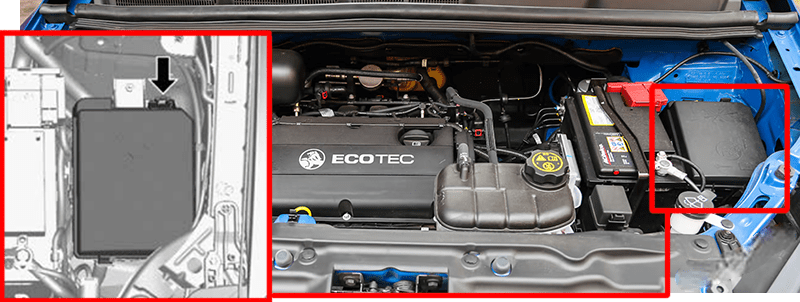
Fuse Box Location
To disengage the cover, lift upwards and remove.
Fuse Box Diagram
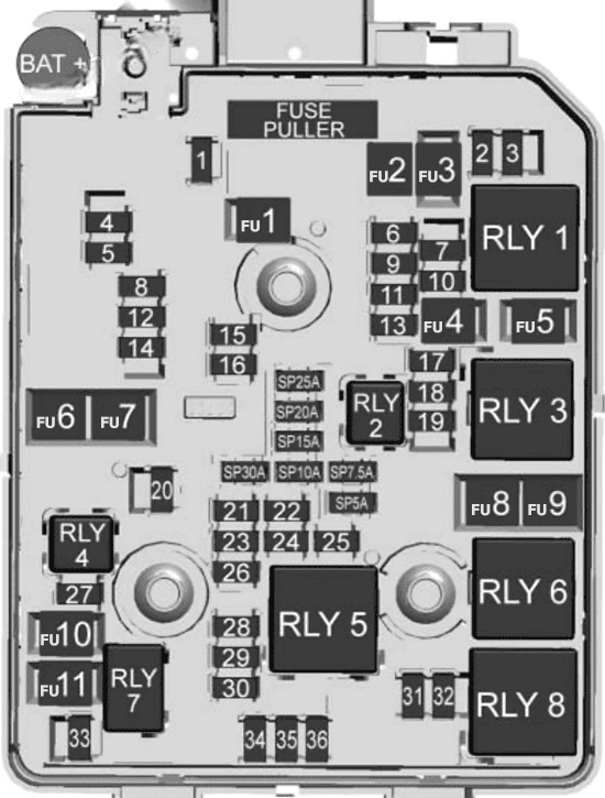
Assignment of the fuses in the engine compartment
| № | Amps | Description |
|---|---|---|
| F1 | 25A | SUNROOF |
| F2 | 7.5A | OSRVM SW |
| F3 | – | – |
| F4 | 25A | SPARE |
| F5 | 30A | EBCM VALVE |
| F6 | 5A | 2015-2016: IBS |
| F7 | 15A | SPARE |
| F8 | 15A | TCM B+ |
| F9 | 5A | BCM RVC |
| F10 | 10A | HDLP LEVELING LH/RH |
| F11 | 20A | REAR WIPER |
| F12 | 25A | RR WDW DEFOG |
| F13 | – | – |
| F14 | 7.5A | OSRVM HEAT |
| F15 | 20A | SPARE |
| F16 | 25A | HEATED SEAT MODULE |
| F17 | 5A | TCM R/C |
| F18 | 5A | ECM R/C |
| F19 | 20A | FUEL PUMP |
| F20 | – | – |
| F21 | 15A | FAN RLY (AUX BEC) |
| F22 | 10A | 2013-2014: COLD START PUMP |
| F23 | 15A | IGNITION COIL / INJECTOR COIL |
| F24 | 10A | WASHER PUMP |
| F25 | – | – |
| F26 | 10A | CANISTER PURGE SOL / WATER VALVE SOL / TURBO WASTEGATE SOL/ TURBO BYPASS SOL / O2 SENSOR PRE/POST |
| F27 | 10A | SPARE |
| F28 | – | – |
| F29 | 20A | ECM PT IGN-1/IGN-2 |
| F30 | 10A | MAF SENSOR |
| F31 | 15A | HIGH BEAM LH |
| F32 | 15A | HIGH BEAM RH |
| F33 | 15A | ECM B+ |
| F34 | 15A | HORN |
| F35 | 10A | A/C CLUTCH |
| F36 | 15A | FRONT FOG LAMP |
| FU1 | 40A | EBCM PUMP |
| FU2 | 30A | FRT WIPER |
| FU3 | 40A | BLOWER |
| FU4 | 30A | IEC R/C |
| FU5 | – | – |
| FU6 | – | – |
| FU7 | 40A | SPARE |
| FU8 | 40A | COOL FAN LOW |
| FU9 | 60A | COOL FAN HIGH |
| FU10 | 30A | EVP |
| FU11 | 30A | STARTER SOL |
| Relays | ||
| RLY 1 | RUN CRANK | |
| RLY 2 | FUEL PUMP | |
| RLY 3 | – | |
| RLY 4 | – | |
| RLY 5 | PT RELAY | |
| RLY 6 | COOL FAN HIGH | |
| RLY 7 | STARTER | |
| RLY 8 | COOL FAN LOW |
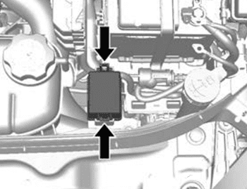
Auxiliary relay box
To disengage the cover, lift upwards and remove.
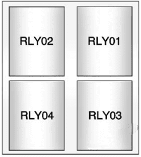
| № | Relays |
|---|---|
| RLY01 | ELECTRIC VACUUM PUMP |
| RLY02 | 2016-2016: COOLING FAN 1 |
| RLY03 | 2016-2016: COOLING FAN 2 |
| RLY04 | — |
Luggage Compartment Fuse Box
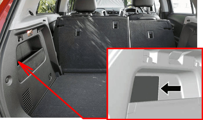
Fuse Box Location
The rear compartment fuse box is located in the passenger side of the rear compartment. To remove the cover, pull outwards.
Fuse Box Diagram
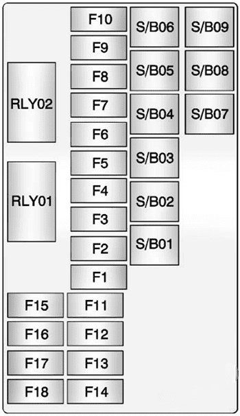
Assignment of the fuses in the trunk
| № | Description | Amps |
|---|---|---|
| F1 | – | – |
| F2 | – | – |
| F3 | – | – |
| F4 | – | – |
| F5 | – | – |
| F6 | – | – |
| F7 | – | – |
| F8 | – | – |
| F9 | – | – |
| F10 | – | – |
| F11 | TRLR MDL | 10A |
| F12 | – | – |
| F13 | – | – |
| F14 | – | – |
| F15 | – | – |
| F16 | – | – |
| F17 | 2013-2014: ISRVM / RVC | 10A |
| F18 | – | – |
| S/B01 | – | – |
| S/B02 | – | – |
| S/B03 | TRLR MDL | 40A |
| S/B04 | AC DC INV | 30A |
| S/B05 | BATT+ | 40A |
| S/B06 | – | – |
| S/B07 | – | – |
| S/B08 | – | – |
| Relays | ||
| RLY1 | IGN | |
| RLY2 | – |