
The Holden Captiva / Captiva 7 (CG, pre-facelift) compact crossover SUV was manufactured from 2006 to 2011. In this article you will find the Holden Captiva 2006, 2007, 2008, 2009 and 2010 fuse box images, information on the location of the fuse boxes in the vehicle and the allocation of each fuse (fuse layout) and relay.
Passenger Compartment Fuse Box
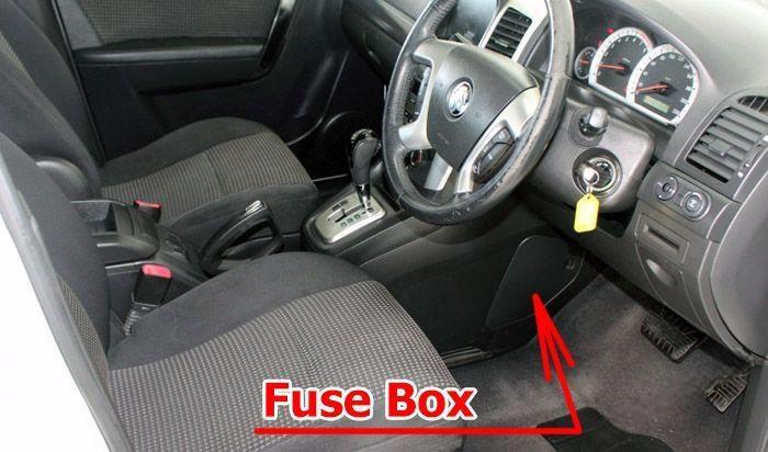
Fuse Box Location
The fuses are located on the left-hand side of the driver’s side footwell. To open the fuse cover, pull the top of the cover outward.
Fuse Box Diagram
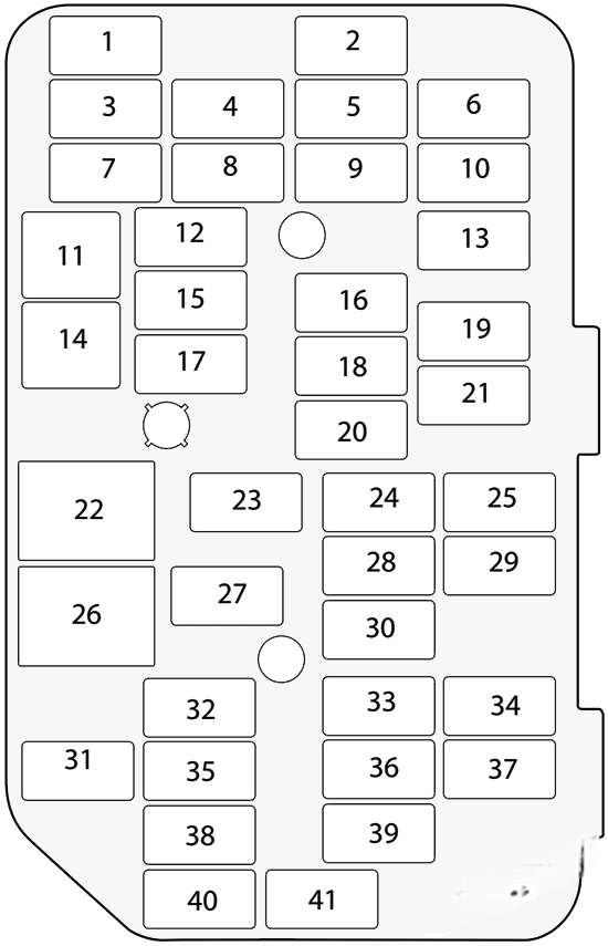
Assignment of the fuses in the passenger compartment
| № | Amps | Allocation |
|---|---|---|
| 1 | 10A | Front mirror |
| 2 | 20A | Door lock |
| 3 | Spare | |
| 4 | 15A | Front door lock |
| 5 | 15A | BCM (VB6) |
| 6 | 20A | APO 1 (Additional power outlet 1) |
| 7 | 20A | Cigar lighter |
| 8 | 20A | APO 2 (Additional power outlet 2) |
| 9 | 15A | BCM (VB3) |
| 10 | 20A | Heat/mat |
| 11 | 20A | Passenger power window |
| 12 | 15A | TCM |
| 13 | 15A | Audio |
| 14 | 20A | Driver’s power window |
| 15 | 15A | Engine |
| 16 | 15A | BCM (VB4) |
| 17 | 10A | XBCM |
| 18 | 15A | BCM (VB5) |
| 19 | 10A | 2006-2007: Trailer |
| 20 | 10A | 2006-2007: RR CLS |
| 21 | 10A | 2006-2007: PKLP-RH |
| 22 | Relay ACC/RAP | |
| 23 | 10A | Lift glass |
| 24 | 15A | Air conditioning |
| 25 | 10A | Air conditioning |
| 26 | Relay run/crank | |
| 27 | 15A | OSRVM HT |
| 28 | 20A | BCM (VB2) |
| 29 | 10A | 2006-2007: SSPS |
| 30 | 15A | BCM (VB7) |
| 31 | 10A | Clock |
| 32 | 10A | Instrument cluster |
| 33 | 2A | Ignition switch |
| 34 | 10A | BCM (VB1) |
| 35 | 10A | Ignition 1 |
| 36 | 10A | Rear defrost |
| 37 | 10A | 2006-2007: CTD Horn |
| 38 | 10A | Airbag |
| 39 | 10A | Airbag |
| 40 | 2A | 2006-2007: WHL S/W |
| 41 | 10A | Front washer |
Engine Compartment Fuse Box
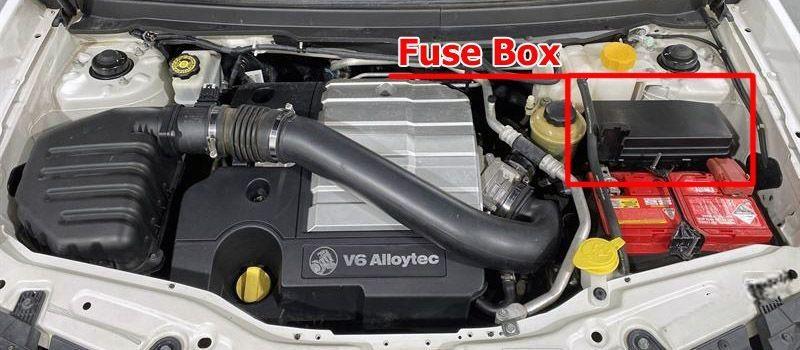
Fuse Box Location
This fuse box is located on the passenger side of the engine compartment, it contains circuit fuses, main fuses and relays. To remove the cover, press the catch on the side of the fuse box toward the engine and release the two tabs at the opposite side.
Fuse Box Diagram
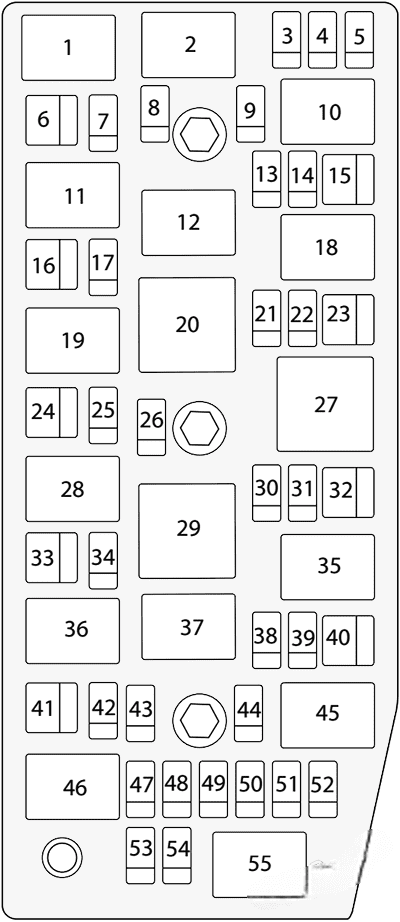
Assignment of the fuses in the engine compartment
| № | Amps | Allocation |
|---|---|---|
| 1 | Starter relay | |
| 2 | Main relay | |
| 3 | 20A | ECM |
| 4 | 15A | Engine 2 |
| 5 | 15A | Engine 1 |
| 6 | 20A | Starter |
| 7 | 10A | Main |
| 8 | 10A | A/C compressor |
| 9 | 15A | Engine 3 |
| 10 | Auxiliary fan relay | |
| 11 | A/C compressor relay | |
| 12 | Main fan relay | |
| 13 | 15A | AWD |
| 14 | 15A | Fuel |
| 15 | 30A | Main fan |
| 16 | 40A | ABS |
| 17 | 20A | ABS |
| 18 | Fuel relay | |
| 19 | Horn relay | |
| 20 | Fan control relay | |
| 21 | Spare | |
| 22 | 15A | Stop |
| 23 | 30A | Auxiliary fan |
| 24 | 40A | Run |
| 25 | 25A | Wiper |
| 26 | 15A | Horn |
| 27 | Wiper speed relay | |
| 28 | Wiper relay | |
| 29 | Run relay | |
| 30 | 15A | Anti theft |
| 31 | 20A | Sunroof |
| 32 | 40A | Accessory / lgnition |
| 33 | 60A | Battery |
| 34 | 30A | Power seat |
| 35 | Defog relay | |
| 36 | Front fog relay | |
| 37 | Park lamp relay | |
| 38 | 15A | H/light low RH |
| 39 | 15A | H/light low LH |
| 40 | 30A | Defog |
| 41 | 20A | Rear wiper |
| 42 | 15A | H/light high |
| 43 | 15A | Front fog |
| 44 | 10A | Park lamp LH |
| 45 | H/light low relay | |
| 46 | H/light high relay | |
| 47 | Spare | |
| 48 | Spare | |
| 49 | 10A | Park lamp RH |
| 50 | 15A | TCM |
| 51 | 20A | H/light washer |
| 52 | Spare | |
| 53 | Spare | |
| 54 | Spare | |
| 55 | H/light washer relay |
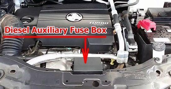
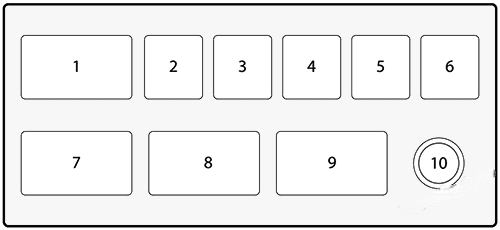
Diesel Auxiliary Fuse Box
| № | Amps | Allocation |
|---|---|---|
| 1 | Relay PTC 3 | |
| 2 | 40A | PTC 3 |
| 3 | 40A | PTC 2 |
| 4 | 40A | PTC 1 |
| 5 | 30A | F/F HTR |
| 6 | 60A | GPCU |
| 7 | Relay PTC 2 | |
| 8 | Relay PTC 1 | |
| 9 | Relay F/F HTR | |
| 10 | B+ |