
The Ford Taurus X full-size crossover SUV was produced from 2008 to 2009. In this article you will find the 2008 and 2009 Ford Taurus X fuse box outline, information on the location of the fuse boxes inside the car and the allocation of each fuse (fuse layout) and relay.
The cigar lighter (power outlet) fuses in the Ford Taurus X are the fuses #13 (power point – instrument panel), #14 (power point – 2nd row), #15 (power point – 3rd row) and #16 (power point – console) in the engine compartment fuse box.Information about the location of the fuse panels in the car, and learn about the assignment of each fuse (fuse layout) and relay.
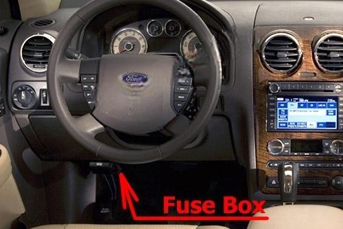
Passenger compartment fuse box
Fuse box location
It is located to the left under the instrument panel.
Fuse box diagram
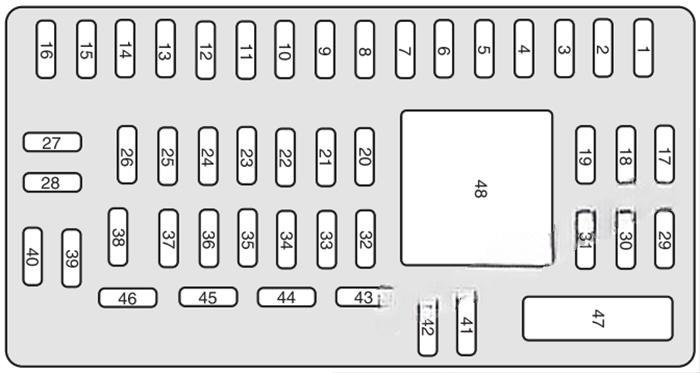
Assignment of the fuses in the Passenger compartment
| № | Amp Rating | Description |
|---|---|---|
| 1 | 30A | Smart window motor |
| 2 | 15A | Brake on/off switch, High-mounted brake lamp |
| 3 | 15A | SDARS, Bluetooth, Family entertainment system (FES)/Rear seat control |
| 4 | 30A | Not used (spare) |
| 5 | 10A | SPDJB logic power |
| 6 | 20 A | Turn signals |
| 7 | 10A | Low beam headlamps (left) |
| 8 | 10A | Low beam headlamps (right) |
| 9 | 15A | Interior lights, Cargo lamps |
| 10 | 15A | Backlighting, Puddle lamps |
| 11 | 10A | All wheel drive |
| 12 | 7.5A | Memory seat/mirror switches, Memory module |
| 13 | 5A | FEPS module |
| 14 | 10A | Power liftgate module |
| 15 | 10A | Climate control |
| 16 | 15A | Not used (spare) |
| 17 | 20A | All power lock motor feeds, Liftgate release |
| 18 | 20A | 2nd row power seat |
| 19 | 25A | Moon roof |
| 20 | 15A | OBDII connector |
| 21 | 15A | Fog lamps |
| 22 | 15A | Park lamps, License lamps |
| 23 | 15A | High beam headlamps |
| 24 | 20A | Horn relay |
| 25 | 10A | Demand lamps/Interior lamps |
| 26 | 10A | Instrument panel cluster |
| 27 | 20A | Adjustable pedal switch |
| 28 | 5A | Radio, Radio start signal |
| 29 | 5A | Instrument panel cluster |
| 30 | 5A | Overdrive cancel switch |
| 31 | 10A | 2008: Compass, Automatic dimming rear view mirror 2009: Not used (spare) |
| 32 | 10A | 2008: Restraint control module 2009: Not used (spare) |
| 33 | 10A | 2008: Not used (spare) 2009: Restraint control module |
| 34 | 5A | AWD module |
| 35 | 10A | Steering rotation sensor, FEPS, Rear park assist, Heated seat modules |
| 36 | 5A | PATS module |
| 37 | 10A | Climate control |
| 38 | 20A | Subwoofer (Audiophile radio) |
| 39 | 20A | Radio |
| 40 | 20A | Spare |
| 41 | 15A | Mic mirror, Moon roof, Front lock switches, Radio |
| 42 | 10A | Not used (spare) |
| 43 | 10A | Not used (spare) |
| 44 | 10A | Not used (spare) |
| 45 | 5A | Relay coils: PDB, Auxiliary A/C, Front and rear wipers, Front blower motor |
| 46 | 7.5A | Occupant Classification Sensor (OCS), Passenger Airbag Deactivation Indicator (PADI) |
| 47 | 30A | Power windows (Circuit Breaker) |
| 48 | — | Delayed accessoiy relay |
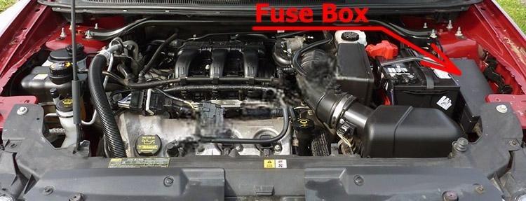
Engine compartment fuse box
Fuse box location
Fuse box diagram
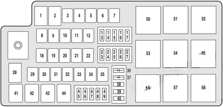
Assignment of the fuses and relays in the Power distribution box
| № | Amp Rating | Description |
|---|---|---|
| 1 | 80A | SPDJB power |
| 2 | 80A | SPDJB power |
| 3 | 30A | Front wipers |
| 4 | — | Not used |
| 5 | 20A | Rear heated seat module |
| 6 | — | Not used |
| 7 | 50A | Engine cooling fan |
| 8 | — | Not used |
| 9 | 40A | Anti-lock Brake System (ABS)/AdvanceTrac pump |
| 10 | 30A | Starter |
| 11 | 50A | Powertrain Control Module (PCM) relay |
| 12 | 20A | ABS/Advance Trac valve |
| 13 | 20A | Power point (instrument panel) |
| 14 | 20A | Power point (2nd row) |
| 15 | 20A | Power point (3rd row) |
| 16 | 20A | Power point (console) |
| 17 | 10A | Alternator |
| 18 | — | Not used |
| 19 | — | Not used |
| 20 | 40A | Rear defroster |
| 21 | 30A | Power seat motors (passenger) |
| 22 | 20A | Heated seat module |
| 23 | 10A | PCM Keep alive power, Canister vent |
| 24 | 10A | A/C clutch relay |
| 25 | 25A | Rear wiper |
| 26 | 20A | Backup relay |
| 27 | 15A | Fuel relay (Fuel pump driver module, Fuel pump) |
| 28 | — | Not used |
| 29 | 30A | Power liftgate |
| 30 | — | Not used |
| 31 | 30A | Auxiliary blower relay |
| 32 | 30A | Driver seat motors, Memory module |
| 33 | 20A | Ignition switch (to SJB) |
| 34 | — | Not used |
| 35 | 40A | Front A/C blower motor |
| 36 | 1A Diode | One-touch start |
| 37 | 1A Diode | Fuel pump |
| 38 | 10A | IVD, Yaw rate sensor |
| 39 | 10A | Fuel diode, PCM |
| 40 | 10A | Auxiliary coolant pump |
| 41 | G8VA relay | A/C clutch |
| 42 | G8VA relay | Fuel pump |
| 43 | G8VA relay | Backup |
| 44 | G8VA relay | Rear wiper |
| 45 | 10A | Speed control deactivate switch, Mass air flow sensor, Inline module VPWR2 |
| 46 | 10A | A/C clutch relay, VPWR3 |
| 47 | 15A | PCM VPWR1 |
| 48 | 15A | PCM VPWR4 |
| 49 | 15A | Heated mirrors |
| 50 | Full ISO relay | PCM relay |
| 51 | — | Not used |
| 52 | — | Not used |
| 53 | Full ISO relay | Rear defrost relay |
| 54 | Full ISO relay | Blower motor relay |
| 55 | Full ISO relay | Starter relay |
| 56 | — | Not used |
| 57 | Full ISO relay | Front wiper relay |
| 58 | — | Not used |