In this article we look at the facelifted fourth generation Ford F-Series Super Duty, available from 2020 to the present. Here you will find the Ford F-250 / F-350 / F-450 / F-550 2020, 2021 and 2022 fuse box diagrams, get information on the location of the fuse boxes in the vehicle and learn about the assignment of each fuse (fuse layout).
Passenger Compartment Fuse Box
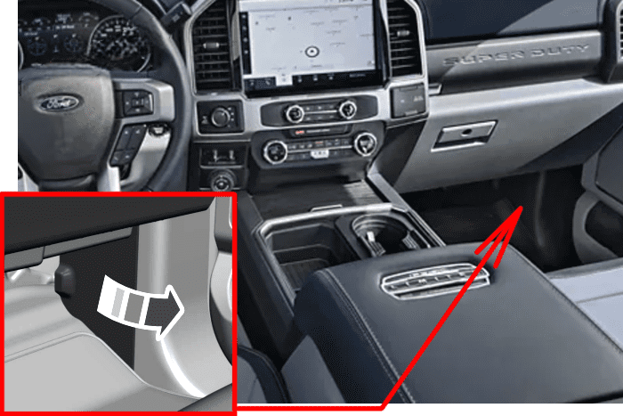
Fuse Box Location
The fuse panel is in the right-hand side of the passenger footwell behind a trim panel. To remove the trim panel, pull it toward you and swing it away from the side. To reinstall it, line up the tabs with the grooves on the panel, and then push it shut.
Fuse Box Diagram
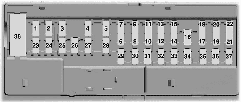
Assignment of the fuses in the passenger compartment (2020-2022)
| № | Rating | Protected Component |
|---|---|---|
| 1 | — | Not used. |
| 2 | 10 A | Driver door pack switch. Power sliding rear window switch. |
| 3 | 7.5 A | Seat memory switch. Power lumbar motor. Wireless charging module. |
| 4 | 20 A | Not used (spare). |
| 5 | — | Not used. |
| 6 | 10 A | Power telescoping mirrors switch. Front power windows switch. |
| 7 | 10 A | Brake on-off switch. |
| 8 | 5 A | Embedded modem. |
| 9 | 5 A | Combined sensor module. |
| 10 | — | Not used. |
| 11 | — | Not used. |
| 12 | 7.5 A | On-board diagnostic module. Smart data link connector. Climate control module. |
| 13 | 7.5 A | Steering column control module. Instrument cluster. |
| 14 | 15 A | Not used (spare). |
| 15 | 15 A | SYNC. Display. |
| 16 | — | Not used. |
| 17 | 7.5 A | Active front steering module. Park aid module. |
| 18 | 7.5 A | Selectable drive modes switch. Select shift switch. |
| 19 | 5 A | Head up display. |
| 20 | 5 A | Ignition switch. Key inhibit solenoid. |
| 21 | 5 A | Head up display. In-vehicle temperature and humidity sensor. |
| 22 | 5 A | Upfitter switches. |
| 23 | 30 A | Driver front door module. |
| 24 | 30 A | Moonroof. |
| 25 | 20 A | Not used (spare). |
| 26 | 30 A | Passenger front door module. |
| 27 | 30 A | Not used (spare). |
| 28 | 30 A | Amplifier. |
| 29 | 15 A | Adjustable pedals switch. |
| 30 | 5 A | Brake on-off output to trailer brake controller and customer access circuits. |
| 31 | 10 A | Remote keyless entry. |
| 32 | 20 A | Radio. |
| 33 | — | Not used. |
| 34 | 30 A | Run/start relay. |
| 35 | 5 A | Not used (spare). |
| 36 | 15 A | Camera module. Lane keeping system. Auto-dimming interior mirror. Rear heated seats. |
| 37 | 20 A | Heated steering wheel. |
| 38 | 30 A | Power windows (Circuit Breaker). |
Engine Compartment Fuse Box
Fuse Box Location
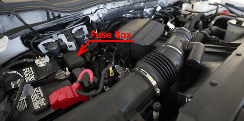
Fuse Box Diagram
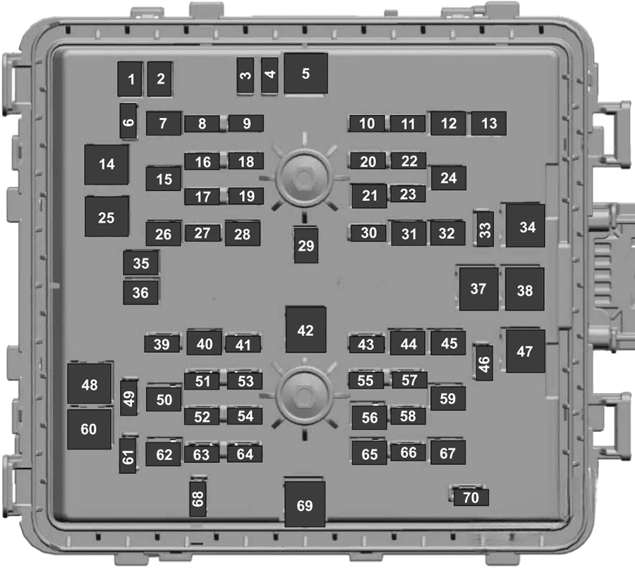
Assignment of the fuses in the engine compartment (2020-2022)
| № | Rating | Protected Component |
|---|---|---|
| 1 | 20 A | Power point 4. |
| 2 | 20 A | Power point 3. |
| 3 | 10 A | Spot light module. |
| 4 | 10 A | Four-wheel drive vacuum solenoid. |
| 5 | 40 A | Active front steering. |
| 6 | 10 A | Snow plow. |
| 7 | 30 A | Trailer tow battery charge. |
| 8 | 10 A | Anti-lock brake system module. |
| 9 | 10 A | Electronic power assisted steering module. |
| 10 | 30 A | Trailer tow park lamps. |
| 11 | 20 A | Horn. |
| 12 | 30 A | Torque overlay. |
| 13 | 30 A | Power sliding rear window. |
| 14 | 40 A | Body control module – battery power in feed 1. |
| 15 | 30 A | Passenger seat power. |
| 16 | 10 A | Powertrain control module. Transmission control module. |
| 17 | 10 A | Blind spot information system. |
| 18 | 10 A | Four-wheel drive module. |
| 19 | 5 A | Adaptive cruise control. |
| 20 | 15 A | Heated mirrors. |
| 21 | 40 A | Heated rear window. |
| 22 | 10 A | On-board diagnostic module. Smart data link connector. |
| 23 | 15 A | Transmission control module. |
| 24 | 30 A | Driver power seat. |
| 25 | 25 A | Voltage quality module. |
| 26 | 30 A | Trailer tow battery charge. |
| 27 | 20 A | Rear heated seats. |
| 28 | 25 A | Glow plug (diesel). |
| 28 | — | Not used (gas). |
| 29 | 40 A | Electric power assisted steering motor. |
| 30 | 10 A | 2020: Heated wiper park. |
| 31 | 20 A | Power point 5. |
| 32 | 25 A | Four-wheel drive module. |
| 33 | 10 A | Alternator sense line 2. |
| 34 | 50 A | Electric cooling fan (gas). Supplemental air heater (diesel). |
| 35 | 20 A | Power point 2. |
| 36 | 20 A | Power point 1. |
| 37 | 60 A | Anti-lock brake system pump. |
| 38 | 60 A | Inverter. |
| 39 | 25 A | Four-wheel drive module. |
| 40 | 30 A | Starter motor solenoid. |
| 41 | 10 A | Tailgate release solenoid. |
| 42 | 40 A | Blower motor. |
| 43 | 10 A | Trailer tow backup lamps. |
| 44 | 40 A | Trailer tow lighting module. |
| 45 | 30 A | Anti-lock brake system valve. |
| 46 | 30 A | Compressed natural gas module power. |
| 47 | 50 A | Supplemental air heater (diesel). |
| 47 | — | Not used (gas). |
| 48 | 50 A | Supplemental air heater (diesel). |
| 48 | — | Not used (gas). |
| 49 | — | Not used. |
| 50 | 30 A | Heated and cooled seats. |
| 51 | 20 A | Powertrain control module. |
| 52 | 15 A | Compressed natural gas (gas). Fuel rail pressure relief control (diesel). |
| 53 | 20 A | Exhaust gas recirculation stepper motor (gas). Universal exhaust gas oxygen sensors (gas). Exhaust gas recirculation cooler bypass (diesel). Urea pump motor controller (diesel). Oxygen sensors. |
| 54 | 20 A | A/C clutch relay power. Fan clutch. |
| 55 | 5 A | Rain sensor. |
| 56 | 30 A | Windshield wipers. |
| 57 | 10 A | Upfitter interface module. |
| 58 | 10 A | Alternator sense line. |
| 59 | 30 A | Power running boards. |
| 60 | 40 A | Body control module – battery power in feed 2. |
| 61 | 10 A | Telescopic mirror motors. |
| 62 | 40 A | Trailer brake control. Aftermarket e-brake access. |
| 63 | 15 A | Multi-contour seats. |
| 64 | 20 A | Ignition coil (gas). Glow plug module (diesel). Nitrogen oxide module (diesel). Urea level and quality sensor (diesel). |
| 65 | 30 A | Fuel pump. |
| 66 | 10 A | A/C clutch solenoid. |
| 67 | 40 A | Auxiliary lighting module. |
| 68 | 10 A | Powertrain control module. |
| 69 | 60 A | Body control module power. |
| 70 | 30 A | Trailer tow stop and turn lamps. |
