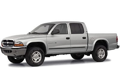
In this article we take a look at the second-generation Dodge Dakota, produced from 1996 to 2000. Here you will find the 1996, 1997, 1998, 1999 and 2000 Dodge Dakota fuse box outline, information on the location of the fuse boxes inside the car and the allocation of each fuse (fuse layout) and relay.
Cigar lighter (socket) fuses in the Dodge Dakota: Fuse #15 in the instrument panel fuse box and fuse #2 (diesel) or #4 (petrol) in the engine compartment fuse box.
Passenger Compartment Fuse Box
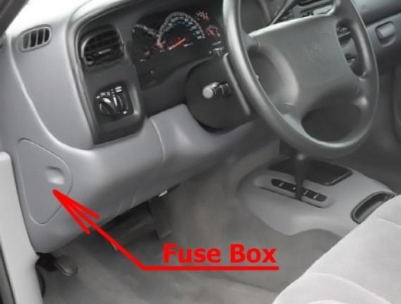
Fuse box location
The fuse panel is located behind the cover on the driver’s side of the dashboard.
Fuse Box Diagram
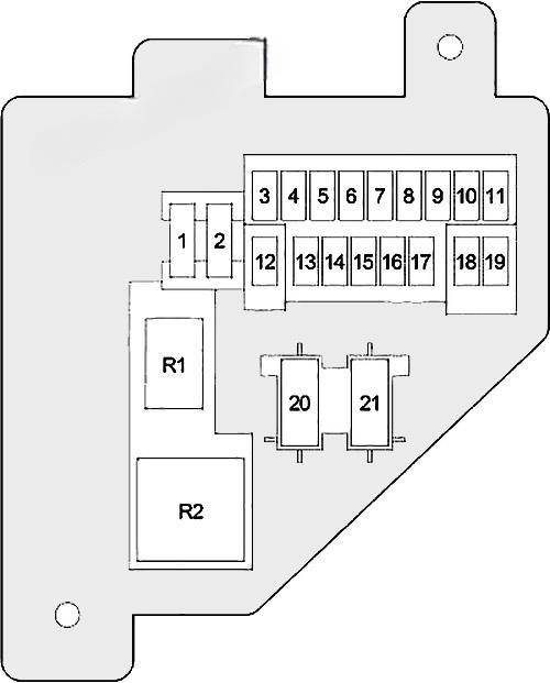
Assignment of fuses in the passenger compartment
| № | Amp Rating | Description |
|---|---|---|
| 1 | 20 | Headlamp Flasher Relay, Air Conditioner Compressor Clutch Relay, Horn Relay, Central Timer Module (VTSS) |
| 2 | 15 | Park/Neutral Position Switch (Automatic Transmission), Back-Up Lamp Switch (Manual Transmission) |
| 3 | 10 | ABS |
| 4 | 15 | Instrument Cluster |
| 5 | 5 | A/C Heater Control, Heater Control (except A/C), Ash Receiver Lamp, Radio, Instrument Cluster |
| 6 | 20 | Wiper Relay, Multi-Function Switch, Central Timer Module, Wiper Motor |
| 7 | 15 | Blower Motor Relay, Air Conditioner Compressor Clutch Relay |
| 8 | 10 | Radio |
| 9 | 10 | Gasoline: Powertrain Control Module, Fuel Pump Relay, Automatic Shut Down Relay, Radiator Fan Relay; Diesel: Engine Control Module, Fuel Heater Relay |
| 10 | 15 | Combination Flasher |
| 11 | 10 | EVAP/Purge Solenoid, Overhead Console, Central Timer Module |
| 12 | 15 | Glove Box Lamp, Radio, Data Link Connector, Underhood Lamp/Switch, Dome Lamp, Overhead Console, Power Mirror Switch |
| 13 | 20 | Central Timer Switch, Power Window/Door Lock Switch |
| 14 | 15 | Headlamp Switch (City Lamp, Tail/Stop Lamp, License Lamp, A/C Heater Control, Heater Control (except A/C), Ash Receiver Lamp, Radio, Instrument Cluster) |
| 15 | 15 | Cigar Lighter |
| 16 | – | Not Used |
| 17 | 10 | Instrument Cluster |
| 18 | 10 | Airbag Control Module |
| 19 | 10 | Airbag Control Module, Passenger Airbag On/Off Switch |
| Circuit Breaker | ||
| 20 | 25 | Power Window/Door Lock Switch |
| 21 | – | Not Used |
| Relay | ||
| R1 | Horn | |
| R2 | Combination Flasher |
Engine Compartment Fuse Box
Fuse box location
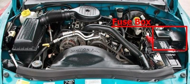
Fuse Box Diagram
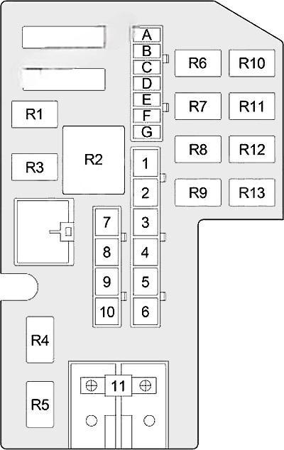
Assignment of fuses and relay in the engine compartment
| № | Amp Rating | Description |
|---|---|---|
| A | 15 or 25 | Gasoline (15A): Oxygen Sensor; Diesel (25A): Air Conditioner Compressor Clutch Relay, Engine ControlModule, Powertrain Control Module, Electric Vacuum Modulator |
| B | 15 | Left Headlamp |
| C | 20 | Fog Lamp Relay |
| D | 25 | Combination Flasher |
| E | 20 | Stop Lamp Switch |
| F | 10 or 20 | Gasoline (20A): Transmission Control Relay; Diesel (10A): Automatic Shut Down Relay, Powertrain Control Module |
| G | 15 | Right Headlamp |
| 1 | 20 or 50 | Gasoline (20A): Powertrain Control Module, Fuel Pump Relay; Diesel (50A): Fuel Heater Relay |
| 2 | 20 or 30 | Gasoline (30A): Radiator Fan Relay; Diesel (20A): Power Outlet |
| 3 | 50 | Gasoline (30A): Automatic Shut Down Relay (Fuel Injector, Ignition Coil, Powertrain Control Module, Fuse: “A”); Diesel (50A): Automatic Shut Down Relay (Fuel Injection Pump, Glow Plug Relay, Fuse: “A”) |
| 4 | 20 or 50 | Gasoline (20A): Power Outlet; Diesel (50A): Glow Plug Relay |
| 5 | 40 | Blower Motor Relay |
| 6 | 50 | Glow Plug Relay (Diesel) |
| 7 | 50 | Passenger Compartment Fuses: “1”, “4”, “12”, “13”, “14”, “21” |
| 8 | 30 | ABS |
| 9 | 40 | Starter Relay, Ignition Switch (Passenger Compartment Fuses: “2”,”3″, “7”, “18”, “20”), Radiator Fan Relay, Fuel Pump Relay, Automatic Shut Down Relay |
| 10 | 40 | Ignition Switch (Starter Relay, Passenger Compartment Fuses: “6”, “8”, “9”, “10”, “11”, “15”, “16”, “17”, “19”) |
| 11 | 140 | Generator |
| Relay | ||
| R1 | Wiper | |
| R2 | Blower Motor | |
| R3 | Starter | |
| R4 | Not Used | |
| R5 | Fog Lamp | |
| R6 | Not Used | |
| R7 | Transmission Control (Gasoline) | |
| R8 | Air Conditioner Compressor Clutch | |
| R9 | Automatic Shut Down | |
| R10 | Not Used | |
| R11 | Radiator Fan (Gasoline) | |
| R12 | Headlamp Flasher | |
| R13 | Fuel Pump (Gasoline) |
