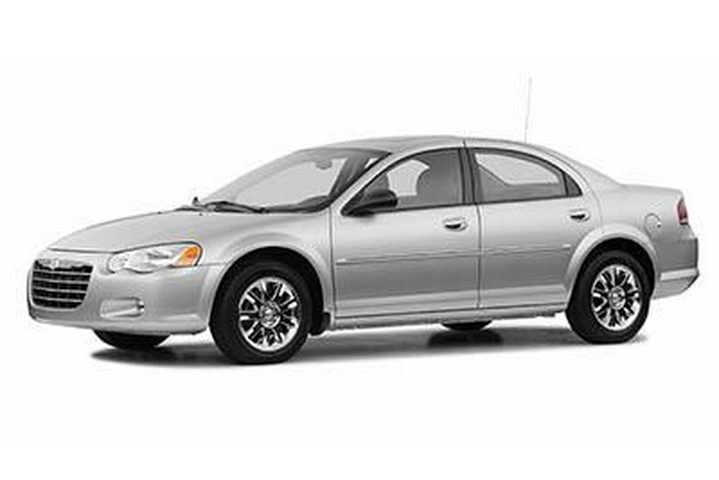
In this article we take a look at the second-generation Chrysler Sebring (ST-22/JR), produced from 2001 to 2006. Here you will find the Chrysler Sebring 2001, 2002, 2003, 2004, 2005 and 2006 fuse box outline, information on the location of the fuse boxes inside the car and the allocation of each fuse (fuse layout).
Information from the 2004-2006 owner’s manual is used. The location and function of the fuses may be different in earlier cars.
The fuses for the cigar lighter socket in the Chrysler Sebring are fuse #2 in the engine compartment fuse box (sedan) or fuses #4, 9 and 16 in the interior fuse box (coupe).
Underhood Fuse Box (Sedan)
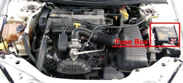
Fuse box location
A Power Distribution Center is located in the engine compartment near the air cleaner.
Fuse box diagram (Sedan)
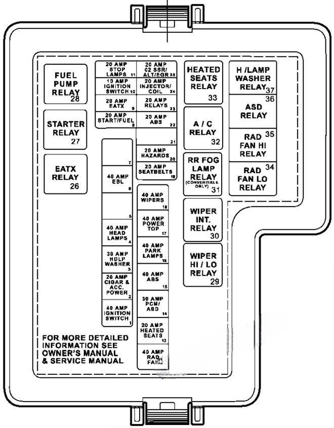
This information applies to vehicles built without the fuse and relay numbering embossed on the Power Distribution Center Top Cover
Assignment of the fuses in the Power Distribution Center (Sedan)
| № | Circuit | Amp |
|---|---|---|
| 1 | Ignition Switch | 40A |
| 2 | Cigar & Acc. Power | 20A |
| 3 | HDLP Washer | 30A |
| 4 | Headlamps | 40A |
| 5 | – | – |
| 6 | EBL | 40A |
| 7 | – | – |
| 8 | Start/Fuel | 20A |
| 9 | EATX | 20A |
| 10 | Ignition Switch | 10A |
| 11 | Stop Lamps | 20A |
| 12 | Radiator Fan | 40A |
| 13 | Heated Seats | 20A |
| 14 | PCM/ASD | 30A |
| 15 | ABS | 40A |
| 16 | Park Lamps | 40A |
| 17 | Power Top | 40A |
| 18 | Wipers | 40A |
| 19 | Seat Belts | 20A |
| 20 | Hazards | 20A |
| 21 | – | – |
| 22 | ABS | 20A |
| 23 | Relays | 20A |
| 24 | Injector/Coil | 20A |
| 25 | O2 SSR/ALT/EGR | 20A |
| Relays | ||
| R1 | HEADLAMP WASHER RELAY | |
| R2 | AUTO SHUT DOWN RELAY | |
| R3 | HIGH SPEED RADIATOR FAN RELAY | |
| R4 | LOW SPEED RADIATOR FAN RELAY | |
| R5 | HEATED SEAT RELAY | |
| R6 | A/C COMPRESSOR CLUTCH RELAY | |
| R7 | REAR FOG LAMPS RELAY | |
| R8 | FRONT WIPER ON/OFF RELAY | |
| R9 | FRONT WIPER HIGH/LOW RELAY | |
| R10 | FUEL PUMP RELAY | |
| R11 | STARTER MOTOR RELAY | |
| R12 | TRANSMISSION CONTROL RELAY |
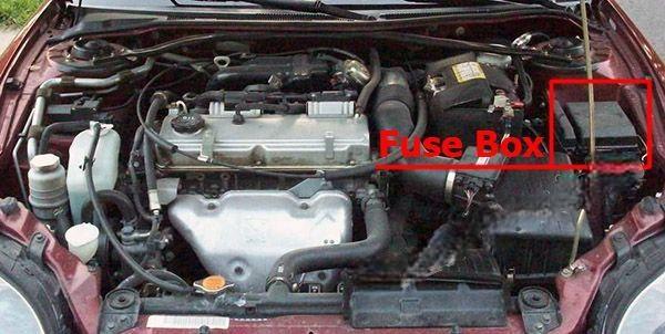
Underhood Fuse Box (Coupe)
Fuse box location
A Power Distribution Center is located in the engine compartment; near the air cleaner.
Fuse Box Diagram
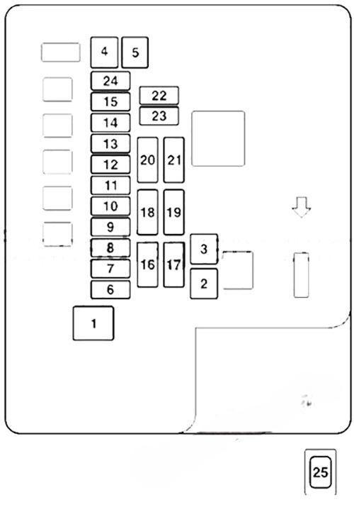
Assignment of the fuses in the Power Distribution Center (Coupe)
| № | Circuit | Amp |
|---|---|---|
| 1 | Fuse (B+) | 60A |
| 2 | Radiator Fan Motor | 50A |
| 3 | Anti-Lock Braking System | 60A |
| 4 | Ignition Switch | 40A |
| 5 | Electric Window Controls | 30A |
| 6 | Fog Lights | 15A |
| 7 | – | – |
| 8 | Horn | 15A |
| 9 | Engine Control | 20A |
| 10 | Air Conditioning | 10A |
| 11 | Stop Lights | 15A |
| 12 | – | – |
| 13 | Alternator | 7.5A |
| 14 | Hazard Warning Flasher | 10A |
| 15 | Automatic Transaxle | 20A |
| 16 | Headlights High Beam (Right) | 10A |
| 17 | Headlights High Beam (Left) | 10A |
| 18 | Headlights Low Beam (Right) | 10A |
| 19 | Headlights Low Beam (Left) | 10A |
| 20 | Positions Lights (Right) | 7.5A |
| 21 | Positions Lights (Left) | 7.5A |
| 22 | Dome Lights | 10A |
| 23 | Audio | 10A |
| 24 | Fuel Pump | 15A |
| 25 | Defroster | 40A |
Interior Fuse Box (Sedan)
Fuse box location
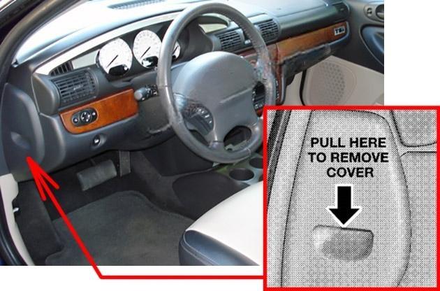
The fuse access panel is behind the end cover at the left side of the instrument panel.
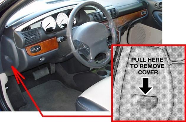
To remove the panel, pull it out, as shown. The identity of each fuse is indicated on the backside of the cover.
Fuse Box Diagram
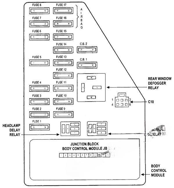
Assignment of fuses in the interior fuse box (Sedan)
| Cavity | Amp | Circuit |
|---|---|---|
| 1 | 30 Amp Green | Blower Motor |
| 2 | 10 Amp Red | Right High Beam Headlight, High Beam Indicator |
| 3 | 10 Amp Red | Left High Beam Headlight |
| 4 | 15 Amp Blue | Power Door Lock Switch Illumination, Transmission Range Switch, Daytime Running Light Module (Canada), Power Windows, Anti-lock Brake System Module |
| 5 | 10 Amp Red | Power Door Lock and Door Lock Arm/Disarm Switches, Vanity, Reading, Map, Rear Seating, Ignition, and Trunk Lights, Illuminated Entry, Radio, Power Antenna, Data Link Connector, Body Control Module, Power Amplifier |
| 6 | 10 Amp Red | Heated Rear Window Indicator |
| 7 | 20 Amp Yellow | Instrument cluster illumination, Park and tail Lights |
| 8 | 20 Amp Yellow | Power Receptacle, Horns, Ignition, Fuel, Start |
| 9 | 15 Amp Blue | Power Door Lock Motors (Body Control Module) |
| 10 | 20 Amp Yellow | Daytime Running Light Module (Canada) |
| 11 | 10 Amp Red | Instrument Cluster, Transmission Control, Park/Neutral Switch, Body Control Module |
| 12 | 10 Amp Red | Left Low beam Headlight |
| 13 | 20 Amp Yellow | Right Low Beam Headlight, Fog Light Switch |
| 14 | 10 Amp Red | Radio |
| 15 | 10 Amp Red | Turn Signal and Hazard Flashers, Wiper Switch, Seat Belt Control Module, Wiper Relays, Rear Window Defroster Relay |
| 16 | 10 Amp Red | Airbag Control Module |
| 17 | 10 Amp | Airbag Control Module |
| 18 | 20 Amp C/BRKR | Power Seat Switch. Remote Trunk Release |
| 19 | 30 Amp C/BRKR | Power Windows |
Interior Fuse Box (Coupe)
Fuse box location
The fuse access panel is behind the end cover at the left side of the instrument panel.
Fuse Box Diagram
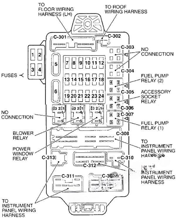
Assignment of fuses in the interior fuse box (Coupe)
| Cavity | Circuit | Amp |
|---|---|---|
| 1 | Audio | 20A |
| 2 | – | – |
| 3 | Sunroof | 20A |
| 4 | Accessory Socket | 15A |
| 5 | Rear Window Defogger | 30A |
| 6 | Heater | 30A |
| 7 | – | – |
| 8 | – | – |
| 9 | Accessory Socket | 15A |
| 10 | Door Lock | 15A |
| 11 | Rear Window Wiper | 15A |
| 12 | – | 15A |
| 13 | Relay | 7.5A |
| 14 | Electric Remote-Controlled Outside Mirror | 7.5A |
| 15 | – | – |
| 16 | Cigarette lighter | 15A |
| 17 | Engine Control | 7.5A |
| 18 | Winshield Wiper | 20A |
| 19 | Door Mirror Heater | 7.5A |
| 20 | Relay | 7.5A |
| 21 | Cruise Control | 7.5A |
| 22 | Back Up Light | 7.5A |
| 23 | Gauge | 7.5A |
| 24 | Engine Control | 10A |
