
In this article you will find the fuse box diagrams for BYD Atto 3 2022 and 2023, get information about the location of the fuse boxes in the car and learn about the assignment of each fuse (fuse layout).
Instrument Panel Fuse Box
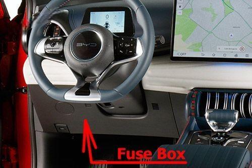
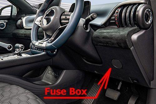
Fuse Box Location
The dashboard panel fuses are located under the driver side of the dashboard. Remove the body fuse under the dashboard panel to repair.
Left-hand drive vehicles
Right-hand drive vehicles
Fuse Box Diagram
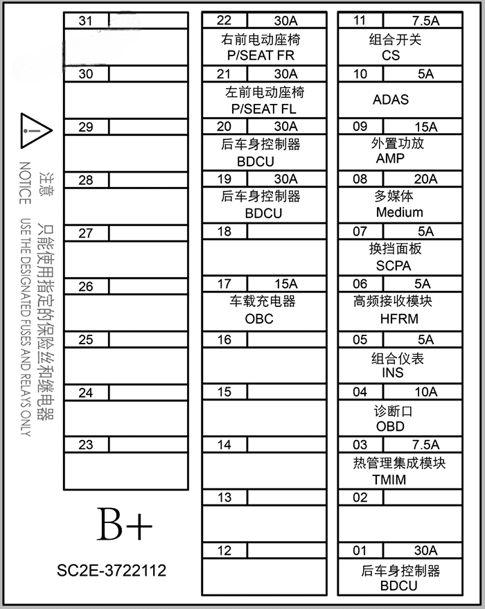
Assignment of the fuses in the dashboard
| № | Amps | Protected Component or Circuit |
|---|---|---|
| 01 | 30A | Rear body control module |
| 02 | – | – |
| 03 | 7.5A | Integrated thermal management module |
| 04 | 10A | Diagnosis port |
| 05 | 5A | Instrument cluster |
| 06 | 5A | High-frequency receiving module |
| 07 | 5A | Gearshift panel |
| 08 | 20A | Infotainment system |
| 09 | 15A | External amplifier |
| 10 | 5A | ADAS |
| 11 | 7.5A | Combination switch |
| 12 | – | – |
| 13 | – | – |
| 14 | – | – |
| 15 | – | – |
| 16 | – | – |
| 17 | 15A | On-board charger |
| 18 | – | – |
| 19 | 30A | Rear body control module |
| 20 | 30A | Rear body control module |
| 21 | 30A | Left front power seat |
| 22 | 30A | Right front power seat |
| 23 | – | – |
| 24 | – | – |
| 25 | – | – |
| 26 | – | – |
| 27 | – | – |
| 28 | – | – |
| 29 | – | – |
| 30 | – | – |
| 31 | – | – |
Under-Hood Compartment Fuse Box
Fuse Box Location
The fuse under the hood is located on the rear left side of the motor compartment. To open it, remove the trim first, and press the latch.
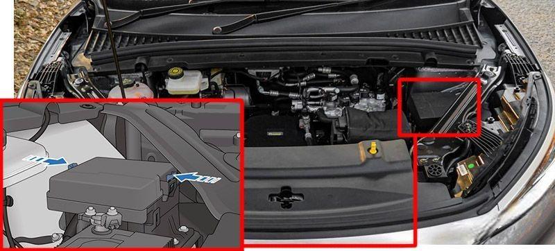
Fuse Box Diagram
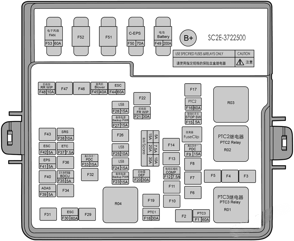
Assignment of the fuses in the front compartment
| № | Amps | Protected Component or Circuit |
|---|---|---|
| F1 | 60A | PTC3 |
| F2 | – | – |
| F3 | – | – |
| F4 | – | – |
| F5 | – | – |
| F6 | – | – |
| F7 | – | – |
| F8 | – | – |
| F9 | 15A | HV all-in-one controller |
| F10 | – | – |
| F11 | – | – |
| F12 | 7.5A | Electric compressor |
| F13 | – | – |
| F14 | – | – |
| F15 | 5A | Brake light switch |
| F16 | 60A | PTC2 |
| F17 | – | – |
| F18 | 30A | PTC1 |
| F19 | – | – |
| F20 | 30A | Rear windshield defroster |
| F21 | 30A | Front wiper |
| F22 | – | – |
| F23 | 15A | Auxiliary power |
| F24 | 15A | USB |
| F25 | 10A | USB |
| F26 | – | – |
| F27 | 15A | Auxiliary power |
| F28 | 15A | USB |
| F29 | – | – |
| F30 | 60A | ESC |
| F31 | – | – |
| F32 | – | – |
| F33 | 15A | HV all-in-one controller |
| F34 | – | – |
| F35 | 5A | Rear body control module |
| F36 | – | – |
| F37 | 7.5A | ETC |
| F38 | 10A | SRS |
| F39 | 5A | ADAS |
| F40 | – | – |
| F41 | 5A | EPS |
| F42 | 5A | ESC |
| F43 | – | – |
| F44 | 60A | ESC |
| F45 | 40A | Blower |
| F46 | – | – |
| F47 | – | – |
| F48 | 10A | Rear Wiper |
| F49 | 200A | Battery |
| F50 | 70A | C-EPS |
| F51 | – | – |
| F52 | – | – |
| F53 | 60A | Electric fan |