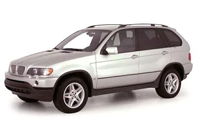
In this article we focus on the first generation BMW X5 (E53), produced from 1999 to 2006. Here you will find the BMW X5 2000, 2001, 2002, 2003, 2004, 2005, 2006 car wiring diagram, information about the location of the fuse boxes inside the car, as well as the allocation of the individual fuses (fuse layout) and relays.
Fuse box in the glove compartment
Fuse Box Location
Open the glove compartment, unhook the two holders at the top, pull the panel down.
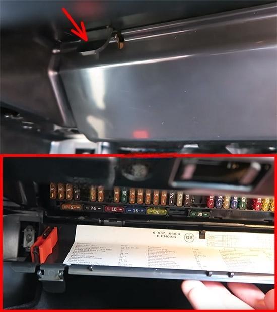
Fuse box diagram

Fuse layout may differ! Your exact fuse allocation scheme is located under this fusebox.
Assignment of the fuses in the glove compartment
| № | A | Component |
|---|---|---|
| F1 | 5A | Data bus connection, instrument panel |
| F2 | 5A | Lamps control module |
| F3 | 5A | Heater/air conditioning (AC) (until 02/01) |
| F4 | 5A | Ignition coil relay |
| F5 | 7,5A | Alternator, engine oil level sensor, fuse box/relay plate cooling fan motor |
| F6 | 5A | Interior rearview mirror, parking aid control module(until 02/04), tyre pressure monitor control module |
| F7 | 5A | Ignition coil relay |
| F8 | 5A | Instrument illumination |
| F9 | 5A | Airbag, brake pedal position (BPP)switch, lamps control module |
| F10 | 15A | Horn |
| F11 | 5A | Immobilizer |
| F12 | 5A | Instrument illumination, steering position sensor |
| F13 | 5A | Alarm system, interior rearview mirror |
| F14 | 5A | Multifunction control module 1 |
| F15 | 5A | Tyre pressure monitor control module (until 02/04) |
| F16 | 5A | Ignition switch |
| F17 | 5A | Interior lamps control module |
| F18 | – | – |
| F19 | – | – |
| F20 | 30A | Door function control module, driver |
| F21 | 30A | Electric seats |
| F22 | – | – |
| F23 | – | – |
| F24 | 30A | Door function control module, passenger |
| F25 | 25A | Charging socket, cigarette lighter |
| F26 | 30A | Ignition main circuits relay |
| F27 | 20A | Multifunction control module 1 |
| F28 | 30A | Headlamp washers |
| F29 | 10A | Airbag |
| F30 | – | – |
| F31 | 5A | Engine management |
| F32 | 5A | Ignition main circuits relay, multifunctioncontrolmodule2 |
| F33 | 5A | Cigarette lighter |
| F34 | 7,5A | Heated rear window, heater/air conditioning (AC) |
| F35 | – | – |
| F36 | 5A | Charging socket |
| F37 | 5A | Multifunction control module 2 |
| F33 | – | – |
| F39 | 5A | Clutch pedal position (CPP) switch, immobilizer |
| F40 | 30A | Windscreen wipers |
| F41 | 5A | Rear screen wash/wipe system, multifunction control module 1 |
| F42 | 5A | Interior lamps |
| F43 | 5A | Instrument panel |
| F44 | 5A | Airbag, electric seats |
| F45 | 5A | Instrument panel |
| F46 | 7,5A | Transfer box control module |
| F47 | 25A | Fuel pump (FP) relay |
| F48 | 7,5A | Heater/air conditioning (AC) |
| F49 | – | – |
| F50 | – | – |
| F51 | 10A | Anti-lock brake system (ABS), engine management |
| F52 | 15A | Datalink connector (DLC) (until 09/00) |
| F53 | 25A | Multifunction control module 2 |
| F54 | 15A | Transmission control module(TCM) |
| F55 | 30A | Anti-lock brake system (ABS) |
| F56 | – | – |
| F57 | 15A | Suspension control module |
| F58 | 20A | Sunroof |
| F59 | 20A | Auxiliary heater |
| F60 | 30A | Multifunction control module 1 |
| F61 | 50A | Engine coolant blower motor |
| F62 | 50A | Secondary air injection (AIR) pump relay |
| F63 | 50A | Anti-lock brake system (ABS) |
| F64 | 50A | Heater/air conditioning (AC) |
Relay block under the glove compartment
Fuse Box Location
It is located behind the fuse box.
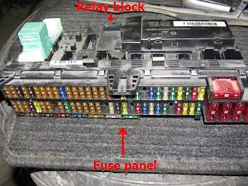
Diagram
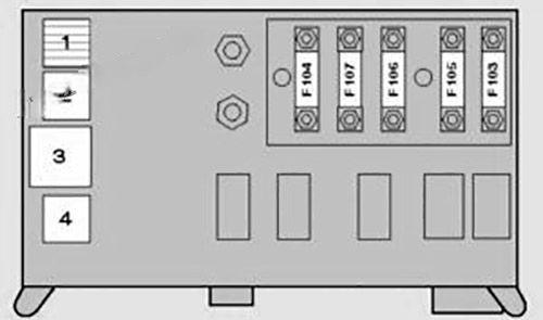
Assignment of the fuses and relays
| № | A | Component |
|---|---|---|
| 1 | Fuel lift pump relay – Diesel | |
| 2 | – | |
| 3 | Interior lamps control module | |
| 4 | Horn relay | |
| F103 | – | – |
| F104 | 100A | Glow plugs |
| F105 | 80A | Immobilizer, ignition switch-4,4/4,6 ( until 02/02) |
| F106 | 50A | Ignition switch, lamps control module |
| F107 | 50A | Lamps control module |
Fuse box in the luggage compartment
Fuse Box Location
It is located on the right side, behind the cover.
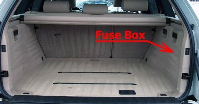
Fuse box diagram

Fuse layout may differ!Assignment of the fuses and relay in the luggage compartment
| № | A | Component |
|---|---|---|
| 1 | Seat heater relay- rear | |
| 2 | Heated rear window relay | |
| 3 | Audio unit relay | |
| 4 | Boot lid/tailgate release relay- lower | |
| 5 | Seat adjustment relay, rear | |
| 6 | Boot lid/tailgate release relay- upper | |
| F72 | 30A | Audio system, navigation system |
| F73 | 7.5A | Ignition coil relay |
| F74 | 10A | Telephone |
| F75 | 5A | Audio system, navigation system |
| F76 | – | – |
| F77 | 30A | Electric seats-rear |
| F78 | 20A | Trailer socket |
| F79 | 7.5A | Suspension control module |
| F80 | 20A | Ignition coil relay |
| F81 | 20A | Rear screen wash/wipe system |
| F82 | – | – |
| F83 | 20A | Charging socket-rear |
| F84 | 7.5A | Boot lid/tailgate lock |
| F85 | 30A | Heated rear window |
| F86 | 5A | Auxiliary heater |
| F87 | 30A | Suspension compressor pumpl |
Fuses and relay in the engine compartment
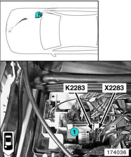
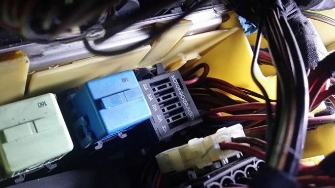
Some relays are located in the mounting block, under the hood (horn relay, glow plug relay, fuel pump relay, headlight washer relay, etc.). Depending on the configuration, there may be fuses.
