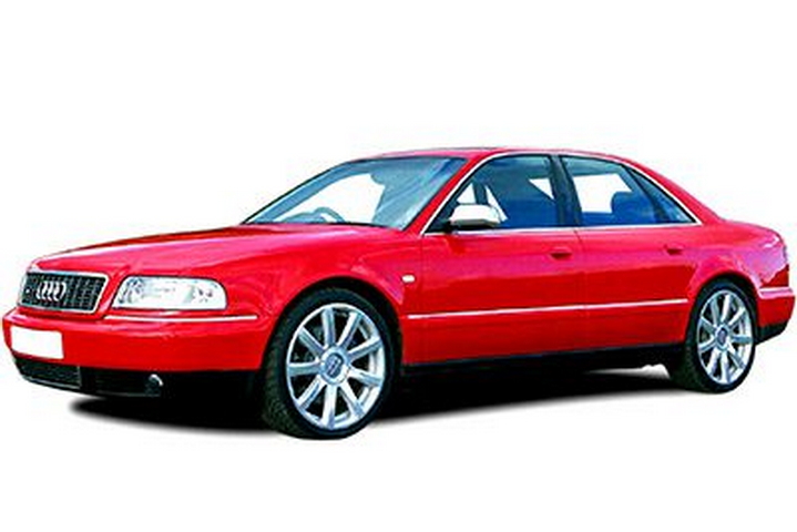
In this article we look at the first generation Audi A8 / S8 (D2/4D), produced from 1994 to 2002. Here you will find the Audi A8 and S8 1998, 1999, 2000, 2001 and 2002 fuse box diagrams, get information on the location of the fuse boxes in the car and learn about the assignment of each fuse (fuse layout) and relay.
Location of fuse and relay boxes
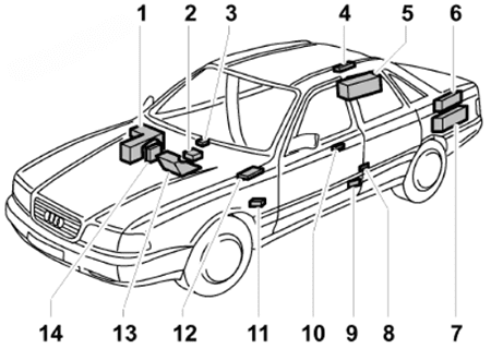
- Electronics box in plenum chamber
- Airbag control unit
- Diagnostic connector in centre console, under ashtray
- Relay and fuse carrier, luggage compartment, right
- Battery / additional battery
- Anti-theft alarm system horn
- Bracket for control units
- Mirror memory control unit, B pillar, driver’s side
- Steering column/belt height adjustment control unit, under carpet, driver’s seat (rear section)
- Heated lock cylinder control unit
- Relay under shelf on driver’s side (auxiliary relay carrier at wheelhouse, left)
- ABS control unit and radiator fan 3rd speed relay, under shelf on driver’s side
- Electronics box, front passenger’s footwell
- Fuse box, right A-pillar, behind trim in front passenger’s footwell
Passenger Compartment Fuse Box
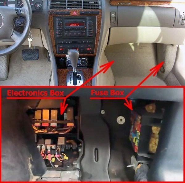
Fuse Box Location
The fuse box is located in the front passenger’s footwell.
Fuse Box Diagram
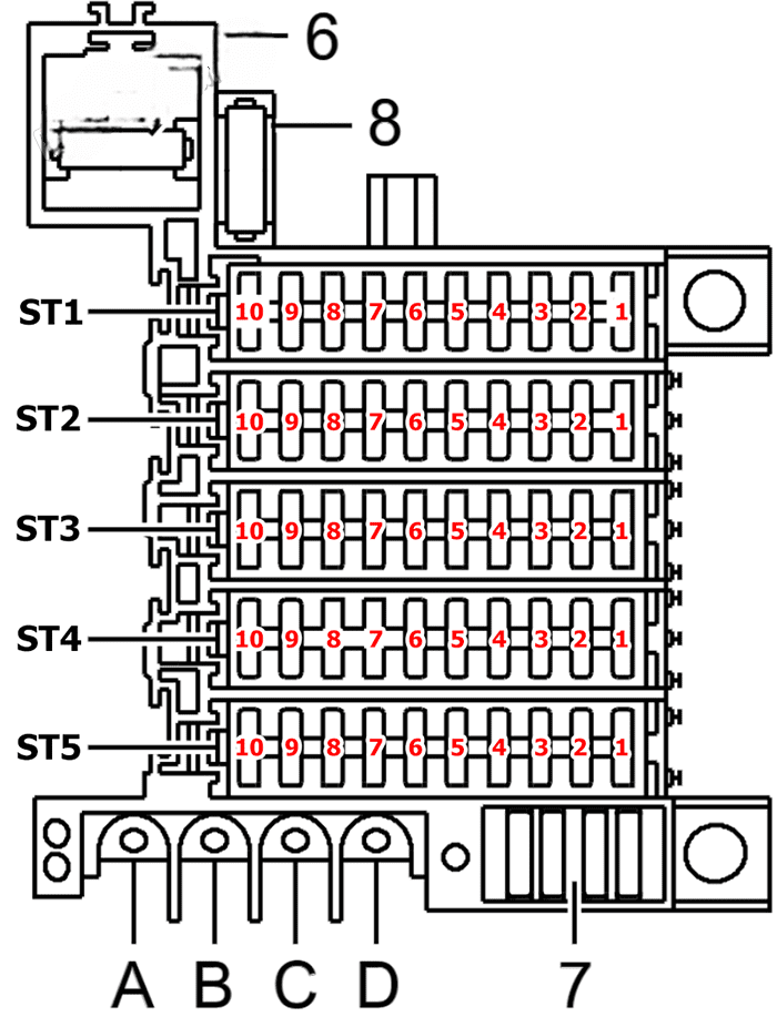
Assignment of the fuses in the passenger’s footwell
| № | Amps | Description |
|---|---|---|
| ST1 | Fuse carrier 1, black | |
| ST2 | Fuse carrier 2, red | |
| ST3 | Fuse carrier 3, yellow | |
| ST4 | Fuse carrier 4, blue | |
| ST5 | Fuse carrier 5, brown | |
| 6 | Secondary air pump fuse | |
| 7 | Spare fuses | |
| 8 | Radiator fan fuse | |
| ST1-1 | 5A | Left side light/parking light, left tail light |
| ST1-2 | 5A | Right side light/parking light, right tail light |
| ST1-3 | 15A | Dipped beam headlight, right |
| ST1-4 | 15A | Dipped beam headlight, left, headlight range control |
| ST1-5 | 10A | Main beam headlight, left |
| ST1-6 | 10A | Main beam headlight, right, main beam warning lamp |
| ST1-7 | 15A | Hazard warning lights |
| ST1-8 | 15A | Dual tone horn |
| ST1-9 | 10A | Diagnostic socket (30a) |
| ST1-10 | 25A | Windscreen wiper system, automatic intermittent wash/ wipe relay |
| ST2-1 | 10A | Mirror heating |
| ST2-2 | 10A | Heated steering wheel |
| ST2-3 | 5A | Display and switch illumination, storage compartment, cup holder, number plate light |
| ST2-4 | 5A | Radiator fan relay, air quality sensor |
| ST2-5 | 15A | Front fog lights, rear fog light, fog lights/rear fog light control unit |
| ST2-6 | 30A | Heated rear window, air conditioner |
| ST2-7 | 5A | Steering angle sensor for ESP |
| ST2-8 | 10A | Hazard warning lights, terminal 75 |
| ST2-9 | 10A | Brake lights |
| ST2-10 | 5A | Heated washer jets |
| ST3-1 | 15A | Bulb monitoring, on-board computer, dash panel insert, parking aid, diagnostic socket (15a), tyre pressure monitor, multi-function steering wheel, headlight range control |
| ST3-2 | 5A | Telephone, telematics, navigation system with screen |
| ST3-3 | 15A | Cigarette lighter, front |
| ST3-4 | 10A | Air conditioner, parking aid, auxiliary heating radio wave receiver, multi-function steering wheel, dash panel insert, solar cell isolation relay, tyre pressure monitor |
| ST3-5 | 10A | Air conditioner |
| ST3-6 | 10A | Cruise control system, reversing lights |
| ST3-7 | 15A | Air conditioner, coolant pump |
| ST3-8 | 10A | Air conditioner compressor, magnetic coupling |
| ST3-9 | 5A | Multi-function steering wheel |
| ST3-10 | 20A | Additional heater control unit, auxiliary heater |
| ST4-1 | 20A | Fuel pump |
| ST4-2 | 30A | V8, V12: Ignition coils V6: Output stage |
| ST4-3 | 20A/10A | Lambda probe heating V8 TDI: Fuel pump |
| ST4-4 | 10A/15A | V8 TDI: Fuel cooling pump V6: Brake servo relay |
| ST4-5 | 5A | Navigation system NS Low |
| ST4-6 | 10A | Navigation system NS Low, chip card reader unit |
| ST4-7 | – | – |
| ST4-8 | 5A | Oil level thermo sender |
| ST4-9 | 25A | Control unit for ABS (ESP), terminal 30 |
| ST4-10 | 10A | Control unit for ABS, terminal 15 |
| ST5-1 | 10A | Illuminated vanity mirrors, central locking, indicator lights for anti-theft alarm system operation, interior lights, reading lamps |
| ST5-2 | 10A | Mirror adjustment, mirror retraction, control units for electric windows , toll pass, rear head restraint adjustment, potentiometer for seat heating, seat adjustment memory |
| ST5-3 | 10A | Entry and footwell lights, ultra-sonic sensor control unit, internal central locking switch, mirror and seat adjustment with memory function, luggage compartment release |
| ST5-4 | 10A | Central locking, automatic anti-dazzle interior mirror, rear roller blind, reading lamp relay |
| ST5-5 | 15A | Central locking |
| ST5-6 | 20A | Sliding/tilting sunroof |
| ST5-7 | 15A | Rear cigarette lighter, heated lock cylinders, adjustable front passenger’s seat |
| ST5-8 | Not used | |
| ST5-9 | 20A | Steering column and belt height adjustment |
| ST5-10 | 20A | Heated front seats, rear roller blind |
Relay Panels
The relay panels are located in electronics box, front passenger’s footwell.
Auxiliary fuse and relay carrier in electronics box (footwell)
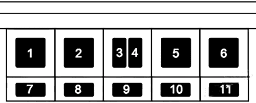
| № | Description |
|---|---|
| 1 | Starter inhibitor relay-automatic gearbox Bridge connection on models with manual gearbox |
| 2 | Adjustable front passenger’s seat relay |
| 3 | Seat adjustment thermo-fuse 2 |
| 4 | Seat adjustment thermo-fuse 1 |
| 5 | Daytime driving light switch-on relay |
| 6 | Fuel cooling relay (TDI) |
| 7 | Hot air blower single fuse |
Micro-central electrics in electronics box (footwell)
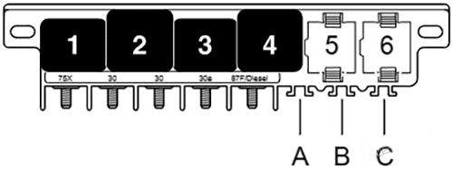
| № | Description |
|---|---|
| 1 | Dual tone horn relay |
| 2 | X contact relief relay |
| 4 | Relay for glow plugs (V6 TDI) Fuel pump relay (V6, V8, V12) Voltage supply relay (V8 TDI) |
| 5 | Electric fuel pump 2 relay (V8 TDI) Radiator fan relay (countries with hot climate, V12) Brake servo relay (V6) |
| 6 | Daytime driving light change-over relay |
Relay carrier in electronics box (footwell)
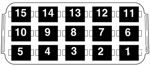
| № | Description |
|---|---|
| 1 | Bulb monitoring device |
| 2 | TDI engine: Fuel pump relay V8, V12 engine: Motronic current supply relay |
| 3 | Fog lights/rear fog light control unit |
| 4 | Automatic intermittent wash/wipe relay |
| 5 | Entry and footwell lighting relay |
| 6 | Bulb monitoring device |
| 7 | Coolant shut-off valve relay |
| 8 | Fog lights/rear fog light control unit |
| 9 | Automatic intermittent wash/wipe relay |
| 10 | Exterior mirror fold system control unit |
| 11 | Reading lamp relay |
| 12 | Servotronic control unit |
| 13 | Solar cell isolation relay |
| 14 | Magnetic coupling relay |
| 15 | Exterior mirror fold system control unit |
Relay carrier under shelf on driver’s side
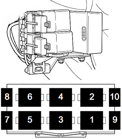
| № | Description |
|---|---|
| 1 | Relay for ABS solenoid valves |
| 2 | ABS return flow pump relay |
| 3 | Multi-function steering wheel control unit |
| 4 | Multi-function steering wheel control unit |
| 6 | Hazard warning light relay Models with trailer coupling: Hazard warning light relay, trailer operation |
| 7 | Front electric window thermo-fuse |
| 8 | Rear electric window thermo-fuse |
Auxiliary relays (for radiator fan)
The first speed, second speed and third speed radiator fan relays are located-in direction of travel-in front of the ABS / ESP control unit under shelf on driver’s side.
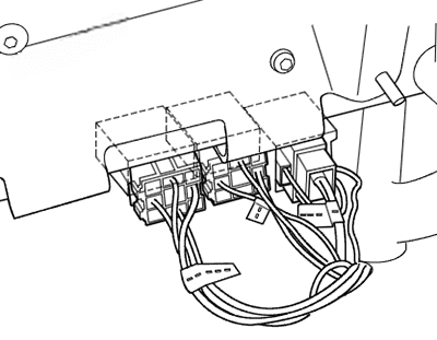
Luggage Compartment Fuse Box
It is on the right side.
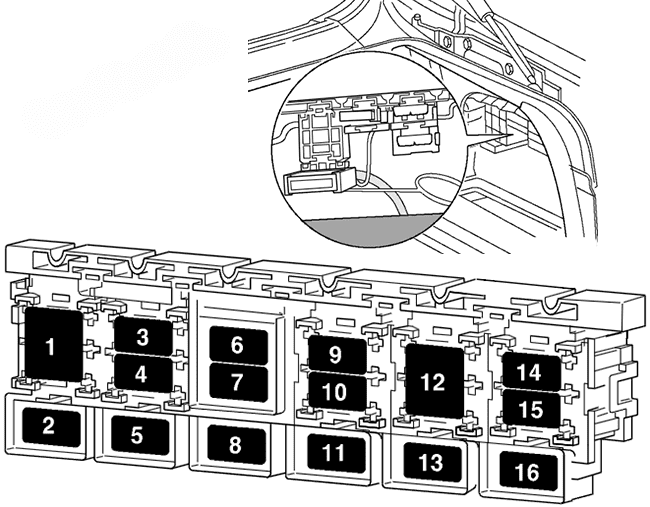
| № | Description |
|---|---|
| 1 | Terminal 30 junction box |
| 2 | ABS hydraulic pump fuse |
| 3 | Heated seats single fuse |
| 4 | Terminal 30 fuse-trailer operation |
| 6 | Radio fuse Navigation fuse |
| 7 | ABS valves fuse |
| 9 | Telephone fuse |
| 14 | Seat adjustment fuse Models without rear seat adjustment: Rear head restraint adjustment fuse |
Engine Compartment Electronics Box
It is on the passenger’s side under a cover.
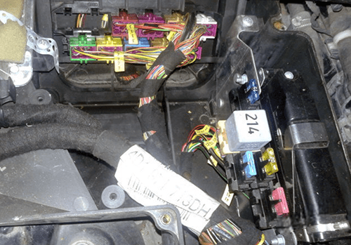
V6, V8 and V12 petrol engines
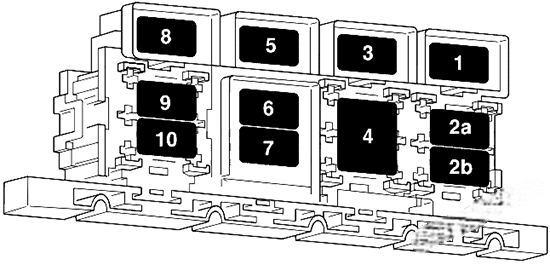
| № | Description |
|---|---|
| 1 | V12: Engine control unit fuse |
| 2a | V12: Secondary air pump relay 1 |
| 2b | V12: Secondary air pump relay 1 V6, V8: Automatic gearbox control unit fuse |
| 3 | V12: Injector fuse |
| 4 | V6, V8: Secondary air pump relay V12: Control element fuse V12: Coolant pump fuse |
| 5 | V12: Automatic gearbox control unit fuse |
| 6 | V6, V8: Injector fuse V12: Continued coolant circulation relay |
| 7 | V6, V8: Control element fuse V12: Continued coolant circulation relay |
| 8 | V12: Control element fuse 2 |
| 9 | V8: Engine control unit fuse V12: Secondary air pump relay 2 |
| 10 | V12: Secondary air pump relay 2 |
V6 diesel engines (TDI)
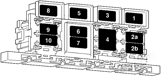
| № | Description |
|---|---|
| 1 | Fuse 1 for glow plugs-engine |
| 2a | Alternator cut-in relay |
| 2b | Alternator cut-in relay |
| 4 | Automatic gearbox control unit fuse |
| 5 | Fuse 2 for glow plugs-engine |
| 6 | Diesel direct injection system relay |
| 7 | Diesel direct injection system relay |
| 9 | Air mass meter fuse |
| 10 | Engine control unit fuse |
V8 diesel engines (TDI)
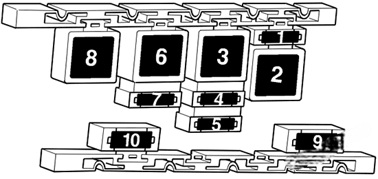
| № | Description |
|---|---|
| 1 | Regulating valve fuse |
| 2 | Glow plug relay 2 |
| 3 | Charge air cooling pump relay |
| 4 | Automatic gearbox control unit fuse |
| 5 | Coolant pump fuse |
| 6 | Alternator cut-in relay |
| 7 | Engine control unit fuse |
| 8 | Relay for glow plugs |
| 9 | Fuse 2 for glow plugs-engine |
| 10 | Fuse 1 for glow plugs-engine |
