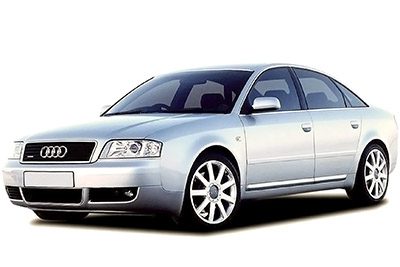
In this article we take a look at the second-generation Audi A6 / S6 / RS6 (C5/4B), produced from 1997 to 2004. Here you will find the Audi A6 1997, 1998, 1999, 2000, 2001, 2002, 2003 and 2004 fuse box outline, information on the location of the fuse boxes in the car and the assignment of each fuse (fuse layout) and relay.
Instrument Panel Fuse Box
Fuse Box Location
The fuses are behind a cover on the driver’s side.
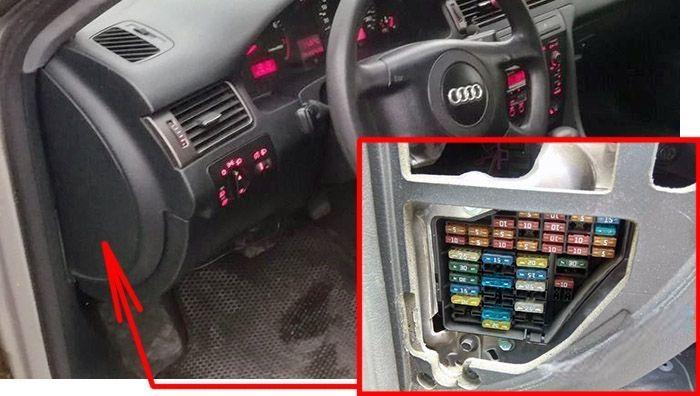
Fuse Box Diagram
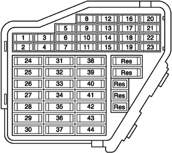
Assignment of the fuses in the instrument panel
| № | Amps | Function/component |
|---|---|---|
| 1 | 5A | Heater element, left washer jet Heater element, right washer jet |
| 2 | 10A | Hazard warning light switch |
| 3 | 5A | Glove box light |
| 4 | 5A | Number plate light |
| 5 | 1997-1999: Dash panel insert, air conditioner, auxiliary heater, exterior mirrors, heated seats, rear window blind, navigation system, parking aid | |
| 5 | 2000-2002: Seat heating, bulb monitoring device, mirror switch, mirror adjustment motors, air conditioner, auxiliary heater, rear roller blind, control unit for: parking aid, navigation system, telephone/telematics, self-levelling suspension, electrical tyre pressure monitoring (alknad models), automatic gearbox (Tiptronic switch) | |
| 5 | 10A | 2003-2004: Oil level/oil temperature sender Compressor regulating valve, air conditioning system High pressure sender Tiptronic switch Tyre pressure monitor control unit Bulb monitoring device Mobile phone operating electronics control unit Control and display unit for air conditioner/Climatronic Air quality sensor Navigation system with CD drive control unit Self-levelling suspension control unit Operating unit to control suspension height Telephone/telematics control unit Control unit for voice control Parking aid control unit Rear roller blind switch |
| 6 | 5A | Central locking control unit |
| 7 | 10A | ABS control unit Steering angle sender TCS/ESP button Cruise control system brake pedal switch (diesel direct injection system) Clutch pedal switch |
| 8 | 5A | Telephone/telematics control unit Control unit for voice control |
| 9 | 10A | Heated exterior mirror, driver’s side Heated exterior mirror, front passenger’s side |
| 10 | 5A | Headlight range control, control unit |
| 11 | 1997-1999: Cruise control system (CCS) | |
| 11 | 5A | 2000-2004: Automatic anti-dazzle interior mirror |
| 12 | 10A | Diagnosis connection |
| 13 | 10A | Brake light switch Brake light bulbs |
| 14 | 1997-2002: Interior lighting control unit, reading lamps, central locking control unit, vanity mirrors, seat adjustment memory | |
| 14 | 10A | 2003-2004: Central locking control unit Memory operating unit, driver’s seat Memory operating unit, front passenger’s seat Luggage compartment release switch Interior monitor switch |
| 15 | 10A | Control unit with display in dash panel insert Solar cell isolation relay Navigation system with CD drive control unit Mirror memory control unit Auxiliary heating radio controlled receiver |
| 16 | 5A | Steering angle sender |
| 17 | 10A | Tyre pressure monitor control unit Self-levelling suspension control unit Two-way radio switch Parking aid control unit |
| 18 | 10A | Main beam bulb, right Main beam warning lamp |
| 19 | 10A | Main beam bulb, left |
| 20 | 15A | Dipped beam bulb, right Headlight range control motor, right |
| 21 | 15A | Dipped beam bulb, left Headlight range control motor, left |
| 22 | 5A | Side light bulb, right Tail light bulb, right |
| 23 | 5A | Side light bulb, left Tail light bulb, left |
| 24 | 25A | Automatic intermittent wash/wipe relay Intermittent wiper control |
| 25 | 30 A | Control and display unit for air conditioner/Climatronic Solar cell isolation relay Fresh air blower Magnetic coupling relay Auxiliary heater relay |
| 26 | 30A | Control and display unit for air conditioner/Climatronic Heated rear window switch |
| 27 | 15A | Heated steering wheel Rear window wiper motor |
| 28 | 20A | Fuel pump (pre-supply pump) Fuel pump control unit Fuel pump relay |
| 29 | 20A/30A | Ignition coil with output stage (engine code BAS) Motronic control unit (engine code BAS) Output stage Ignition coil with output stage Motronic control unit Camshaft timing adjustment valves |
| 30 | 20A | Sliding sunroof adjustment control unit |
| 31 | 1997-1999: Automatic gearbox, reversing lights, cruise control system, automatic anti-dazzle interior mirror | |
| 31 | 2000-2002: Automatic gearbox, reversing lights, diagnostic socket, navigation system, rpm boost, exhaust gas recirculation frequency valve, hazard warning light switch illumination | |
| 31 | 15A | 2003-2004: Starter inhibitor and reversing light relay Hazard warning light switch Reversing light switch Diagnosis connection Multi-function switch Ignition cut-off delay relay Automatic gearbox control unit |
| 32 | 20 A | Injectors Cruise control system switch |
| 33 | 15A | Cigarette lighter Cigarette lighter, rear |
| 34 | 15A | Secondary air pump relay Solenoid valves Secondary air inlet valve Turbocharger divert air valve Air mass meter Heater for lambda probes Intake manifold change-over valve Injectors Cruise control system |
| 35 | 30A | Trailer socket |
| 36 | 15A | Front and rear fog light switch |
| 37 | 20A | Radio Amplifier with bass loudspeaker Aerial selection control unit Operating electronics control unit, navigation Navigation/TV tuner Navigation interface Chip card reader unit |
| 38 | 1997-1999: Luggage compartment light, central locking system | |
| 38 | 20A | 2000-2004: Central locking control unit |
| 39 | 15A | Hazard warning light switch |
| 40 | 25A | Dual tone horn relay |
| 41 | 25A | Relay for ABS solenoid valves (allroad models) |
| 42 | 25A | ABS control unit |
| 43 | 5A | Radio Operating electronics control unit, navigation |
| 44 | 30A | Auxiliary heater relay Solar cells isolation relay 2 Heated driver’s seat regulator Heated front passenger’s seat regulator Heated rear left seat switch with regulator Heated rear right seat switch with regulator |
Relay Panels
13-point relay carrier
It is behind driver’s storage compartment.
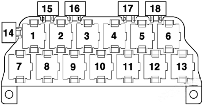
| № | Description |
|---|---|
| 1 | Dual tone horn relay (telematics – USA) |
| 2 | Alternator cut-in relay Alarm system control unit (taxi) Siren relay (police vehicles) Alarm system relay, light change-over (special vehicles) |
| 3 | Solar cell isolation relay Alarm system control unit (taxi) Siren relay (police vehicles) Alarm system relay 2, intermittent main beam (special vehicles) |
| 4 | Starter inhibitor relay Starter inhibitor and reversing light relay |
| 5 | Magnetic coupling relay Auxiliary heater relay |
| 6 | Fog light relay Fuel pump relay (TDI engines) |
| 7 | Multi-function steering wheel control unit |
| 8 | Multi-function steering wheel control unit |
| 9 | Bulb monitoring device |
| 10 | Bulb monitoring device |
| 11 | Exterior mirror fold system control unit |
| 12 | Exterior mirror fold system control unit |
| 13 | Servotronic control unit |
| 14 | Taximeter fuse Fuse E (police vehicles) Hydraulic pump relay fuse (allroad models) |
| 15 | – |
| 16 | Alarm system fuse (taxi) Fuse B (police vehicles) |
| 17 | Taximeter and alarm system fuse (taxi) Fuse C (police vehicles) Intercom system fuse (special vehicles) Fog light fuse (daytime driving lights – Canada) |
Micro-central electrics
It is behind driver’s storage compartment.
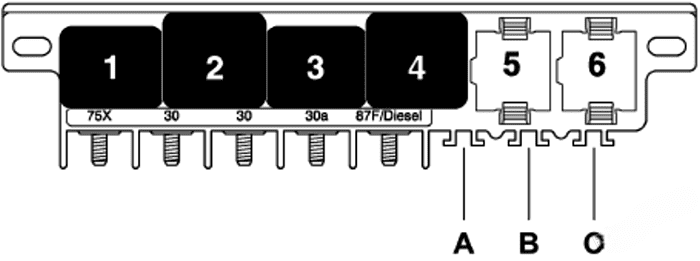
| № | Description |
|---|---|
| 1 | Dual tone horn relay |
| 2 | X contact relief relay |
| 3 | Low range gearing hydraulic pump relay (allroad models) |
| 4 | Fuel pump relay (petrol engines) Relay for glow plugs (diesel engines) |
| 5 | Automatic intermittent wash/wipe relay |
| 6 | Automatic intermittent wash/wipe relay |
| A | 1997-1999: Self-levelling suspension fuse 2000-2004: Steering column adjustment fuse |
| B | Rear roller blind fuse |
| C | For special vehicles |
8-point relay carrier
It is behind driver’s storage compartment, behind micro-central electrics
Left-hand drive vehicles
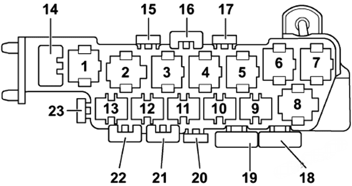
| № | Description |
|---|---|
| 1 | Relay for solenoid valves – ABS with ESP |
| 2 | Radiator fan 2nd speed relay |
| 3 | Radiator fan relay Continued coolant circulation relay |
| 4 | Radiator fan run-on relay |
| 5 | – |
| 6 | Self-levelling suspension compressor relay (allroad models) |
| 7 | Return flow pump relay – ABS with ESP |
| 8 | 2000-2002: Auxiliary heater control unit (small cooling circuit) |
| 8 | 2003-2004: Coolant shut-off valve relay |
| 14 | Seat adjustment thermo-fuse, driver’s side (allroad models) |
| 15 | Fuse for 12V socket |
| 16 | Front electric window thermo-fuse |
| 17 | Rear electric window thermo-fuse |
| 18 | ABS control unit fuse |
| 19 | Radiator fan fuse |
| 20 | Radiator fan control unit fuse |
| 21 | Seat adjustment thermo-fuse, driver’s side Radiator fan fuse (allroad models) |
| 22 | Self-levelling suspension fuse |
| 23 | Self-levelling suspension fuse |
| 24 | Seat adjustment thermo-fuse, front passenger’s side |
Right-hand drive vehicles
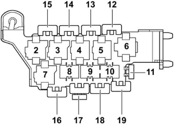
| № | Description |
|---|---|
| 2 | Self-levelling suspension compressor relay (allroad models) |
| 3 | Radiator fan run-on relay |
| 4 | Relay for solenoid valves – ABS with ESP |
| 5 | Radiator fan relay |
| 6 | Return flow pump relay – ABS with ESP |
| 7 | Radiator fan 2nd speed relay |
| 8 | – |
| 9 | – |
| 10 | – |
| 11 | Self-levelling suspension fuse Seat adjustment thermo-fuse, front passenger’s side (RS6 models) |
| 12 | Seat adjustment thermo-fuse, front passenger’s side Radiator fan fuse (RS6 models) |
| 13 | Front electric window thermo-fuse |
| 14 | Rear electric window thermo-fuse |
| 15 | Seat adjustment thermo-fuse, driver’s side |
| 16 | Radiator fan fuse |
| 17 | Radiator fan control unit fuse Fuse for 12V socket (RS6 models) |
| 18 | ABS control unit fuse |
| 19 | Fuse for 12V socket |
Relay carrier
It is on the driver’s side, behind dash panel at central carrier.
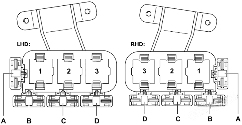
| № | Description |
|---|---|
| 1 | Low heat output relay Brake servo relay |
| 2 | Auxiliary heater relay Solar cells isolation relay 2 (LHD) |
| 3 | High heat output relay |
| A | – |
| B | 1997-1999: Fuse for fuel cooling |
| C | Additional heater fuse 2 Hydraulic pump relay fuse (brake servo) Fuel pump fuse (RS6 models LHD) |
| D | Additional heater fuse Fuel pump fuse (RS6 models RHD) |
3-point relay carrier
In the engine compartment (electronics box).
Version 1
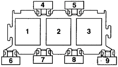
| № | Decription |
|---|---|
| 1 | Additional heater 1 relay (TDI) |
| 2 | Secondary air pump relay |
| 3 | Diesel direct injection system relay |
| 5 | Engine control unit fuse |
| 7 | Fuse for glow plugs (V6 TDI), secondary air pump fuse |
| 8 | Additional heater 2 fuse (TDI), fuse stage 2 (V6 TDI) |
| 9 | Fuse 2 for glow plugs (V6 TDI), fuse for glow plugs (4-cylinder) |
Version 2
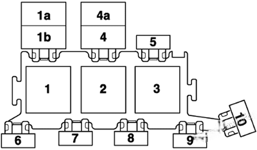
| № | Description |
|---|---|
| 1 | Secondary air pump relay (RS6 models) Auxiliary water pump relay (2000) |
| 1a | Radiator fan relay (allroad models) |
| 1b | Continued coolant circulation relay (allroad models) Additional coolant pump relay (2003) |
| 2 | Secondary air pump relay |
| 3 | Motronic current supply relay (petrol engines) Diesel direct injection system relay (diesel engines) Ignition cut-off delay relay (automatic gearbox 01J) |
| 4 | Fuel cooling pump relay Continued coolant circulation relay (RS6 models) |
| 4a | – |
| 5 | Engine control unit fuse Engine electronics fuse (allroad models) |
| 6 | Not used (left-hand drive vehicles) Fuse 2 for glow plugs (V6 TDI, V8 TDI) Fuse for glow plugs (4-cylinder Radiator fan fuse (allroad models) |
| 7 | Fuse for glow plugs (V6 TDI, V8 TDI) Secondary air pump fuse (petrol engines) Auxiliary heater fuse (right-hand drive vehicles) up to model year 2000 Not used (right-hand drive vehicles) |
| 8 | Auxiliary heater fuse (left-hand drive vehicles) up to model year 2000 Not used (left-hand drive vehicles) |
| 9 | Fuse 2 for glow plugs (V6 TDI, V8 TDI) Fuse for glow plugs (4-cylinder) Radiator fan fuse (allroad models) Coolant pump fuse (RS6 models) Not used (right-hand drive vehicles) |
| 10 | Fuse for fuel cooling Fuse -1- (15) (automatic gearbox 01J) Radiator fan control unit fuse (allroad models) Not used (right-hand drive vehicles) |
Fuses not in relay carrier
- Fuse for auxiliary heater
- Fuse for fuel cooling
- Fuse -1- (15) (automatic gearbox 01J)
- Radiator fan control unit fuse (allroad models)
Additional fuses in plenum chamber
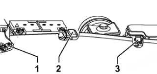
RS6:
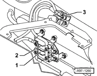
The fuses are located below coolant expansion tank.
| № | Description |
|---|---|
| 1 | Fuse -2- (30) |
| 2 | Fuse -1- (30) |
| 3 | Auxiliary heater fuse Battery screw connection (RS6) |
