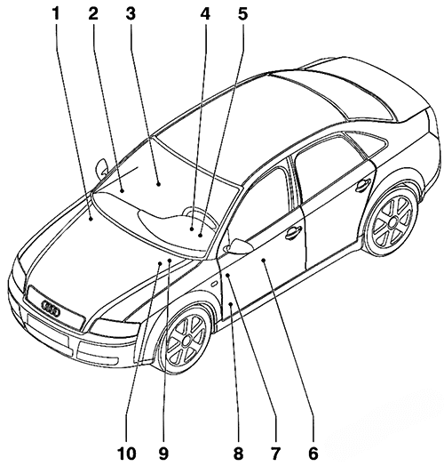
- Main fuse
- Connector station – Right A-pillar
- Connector station – RF seat wiring
- Relay panel (9-position) at Vehicle Electrical System Control Module
- Relay panel (4-position) with threaded connection
- Connector station – LF seat wiring
- Fuse panel
- Connector station – Left A-pillar
- Connector station with threaded connection
- Relay panel (4-position)
Instrument Panel Fuse Box
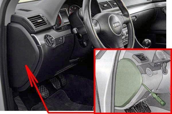
Fuse Box Location
The fuses are behind a cover on the driver’s side. Carefully pry the face cover off the instrument panel using the ignition key or a screwdriver.
Fuse Box Diagram
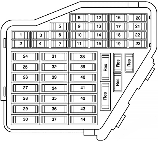
Assignment of the fuses in the instrument panel
| № | Amps | Function/Component |
|---|---|---|
| 1 | 10A | Climatronic Control Module |
| 2 | 5A | Left Footwell Light Right Footwell Light |
| 3 | 5A | Left Washer Nozzle Heater Right Washer Nozzle Heater Left Rear Footwell Light Right Rear Footwell Light |
| 4 | 5A | Coolant Fan Control (FC) Control Module Coolant Fan Control (FC) Control Module 2 |
| 5 | 10A | Rear Window Shade Switch Function Selector Switch II Tiptronic Switch Oil Level Thermal Sensor Rear Window Shade Control Module Navigation System with CD Drive Control Module Parking Aid Control Module |
| 6 | 5A | High Pressure Sensor Sensor for air quality |
| 7 | 10A | Anti-Slip Control Switch Clutch Pedal Switch Brake Pedal Switch ABS Control Module |
| 8 | 5A | Telephone Transceiver Telephone Amplifier |
| 9 | 15A | Brake Booster Relay |
| 10 | 5A | Headlamp Adjuster Headlamp Range Control Module Headlamp Range/Comering Lamp Control Module Left Headlamp Beam Adjusting Motor Right Headlamp Beam Adjusting Motor Right Dynamic Cornering Light Motor |
| 11 | 5A | Airbag Control Module Warning Lamp for airbag off, passenger side |
| 12 | 10A | 16 pin connector, black, diagnostic connector |
| 13 | 10A | Steering Column Electronic Systems Control Module |
| 14 | 10A | Brake Light Switch |
| 15 | 10A | Instrument Cluster Control Module Navigation System with CD Drive Control Module |
| 16 | 5A | Garage Door Opener Control Head Garage Door Opener Control Module |
| 17 | 10A | Rain/Light Recognition Sensor Parking Aid Control Module Tire Pressure Monitoring Control Module |
| 18 | 5A | Left Dynamic Cornering Light Motor |
| 19 | 10A | Left Lront Fog Lamp Right Front Fog Lamp |
| 20 | – | Not used |
| 21 | – | Not used |
| 22 | 15A | Drivers Door Control Module Front Passenger’s Door Control Module |
| 23 | 15A | Left Rear Door Control Module Right Rear Door Control Module |
| 24 | 20A | Comfort System Central Control Module |
| 25 | 30A | Fresh Air Blower Control Module |
| 26 | 30A | Rear Window Defogger Relay |
| 27 | 30A | Towing Recognition Control Module |
| 28 | 20A | Transfer Fuel Pump (FP) Fuel Pump (FP) Control Module |
| 29 | – | Not used |
| 30 | 20A | Power Sunroof Control Module |
| 31 | 15A | Back-Up Light Switch Mass Air Flow (MAF) Sensor Light Recognition Sensor Starting Interlock Relay Transmission Control Module (ICM) |
| 32 | 15A | Trailer Socket |
| 33 | 15A/20A | Cigarette lighter |
| 34 | 20A/30A | 12V Socket |
| 35 | 20A/30A | Socket |
| 36 | 30A | Vehicle Electrical System Control Module Rear Window Wiper Motor |
| 37 | 30A | Vehicle Electrical System Control Module Headlamp Washer Pump |
| 38 | 15A | Radar Interior Monitoring Control Module 1 Alarm Horn Comfort System Central Control Module 8 pin Connector, black, radio connector III |
| 39 | 20A | Radio Amplifier |
| 40 | 25A | High Tone Horn Low Tone Horn Horn Relay |
| 41 | 30A | Auxiliary Heater Control Module Auxiliary Heater Radio Receiver |
| 42 | 25A | ABS Control Module |
| 43 | 15A | Engine Timing Mass Air Flow (MAF) Sensor EGR Potentiometer SIMOS Control Module Power Supply Relay Engine Control Module (ECM) Engine Component Power Supply Relay EGR Vacuum Regulator Solenoid Valve |
| 44 | 30A | Climatronic Control Module |
Connector station – Right A-pillar
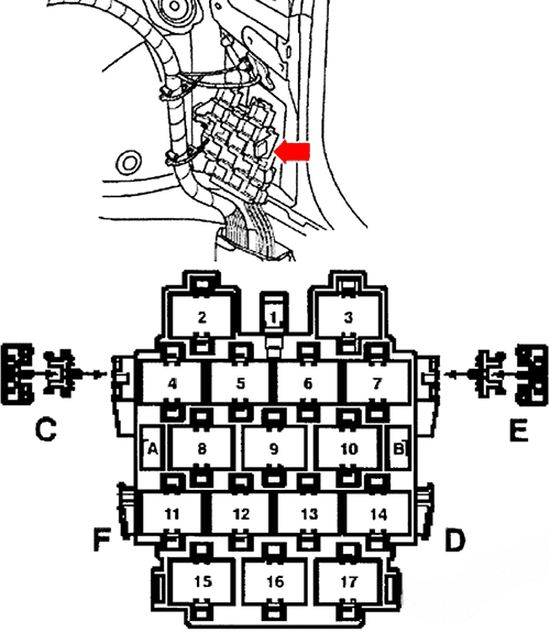
| № | Amps | Circuit Protected |
|---|---|---|
| E | 30A | Power Seat (with manual seats with power lumbar) |
| E | 10A | Power Seat (with power seats) |
Relay Panels
The relay panels are located behind instrument panel, driver’s side.
Relay panel (4-position) with threaded connection
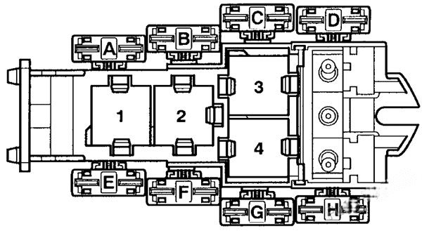
| № | Amp Rating | Circuit Protected |
|---|---|---|
| F | 10A/40A/60A | Fuse (Driver Fan training vehicle) (Not for Engine code BBK, BHF) Coolant Fan Fuse (Engine code BBK, BHF, BNS, BKN) |
| G | 30A/40A/60A | Radiator After run Fuse (Engine code BBK, BHF, BNS, BKN) Coolant Fan Fuse (Not for Engine code BKN, BBK, BHF) |
| H | 40A | ABS Control Module Fuse 1 |
| 3 | NG Engine Throttle Relay 1 (not applicable to USA/CDN models) | |
| 4 | NG Engine Throttle Relay 2 (not applicable to USA/CDN models) | |
| 4 | Alarm – On/Hands-free Control Module (not applicable to USA/CDN models) |
Relay panel (9-position)
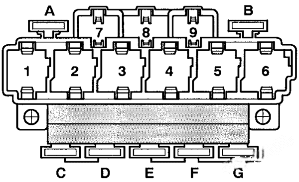
| № | Amps | Circuit Protected |
|---|---|---|
| A | 10A | Rear Shade Circuit Breaker (Right) |
| B | 10A | Rear Shade Circuit Breaker (Left) |
| D | 30A | Power Windows Fuse 2 |
| E | 10A | Driver’s Power Seat Adjustment Circuit Breaker 2 |
| E | 10A | Driver’s Power Seat Adjustment Circuit Breaker 2 (Lumbar Support Adjustment) |
| F | 30A | Power Windows Fuse |
| G | 30A | Trailer Circuit Breaker |
| 1 | Fuel Pump (FP) Relay | |
| 2 | Servotronic Control Module | |
| 3 | Starter Relay 2 (For engine code AUK, BKH, BNS) | |
| 4 | Starter Relay 2 (For engine code AUK, BKH, BNS) Brake Booster Relay (Not applicable for engine code AUK, BKH) | |
| 5 | Rear Window Defogger Relay | |
| 6 | Load Reduction Relay | |
| 8 | Horn Relay | |
| 4 | Brake Booster Relay (Not applicable for engine code AUK, BKH) |
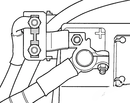
Main Fuse
The main fuse is located on the battery positive post, the fuse is numbered “S88” and has an amperage rating of 150 amps. The battery is located in the plenum chamber on right side of engine compartment.
