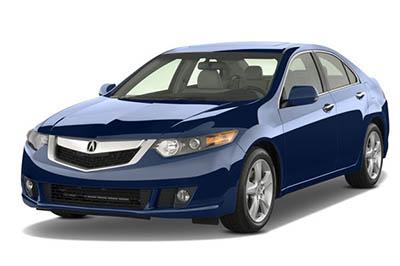
This article is about the second-generation Acura TSX (CU2), produced from 2009 to 2014. Here you will find the Acura TSX 2009, 2010, 2011, 2012, 2013 and 2014 fuse box outline, get information on the location of the fuse boxes inside the car and learn about the assignment of each fuse (fuse layout).
The cigar lighter/power outlet fuses in the Acura TSX are fuse #23 in the driver’s side interior fuse box (front accessory power outlet) and fuse #12 in the passenger’s side interior fuse box (console accessory power outlet).
The under-hood fuse box
Fuse Box Location
The under-hood fuse box is on the driver’s side.
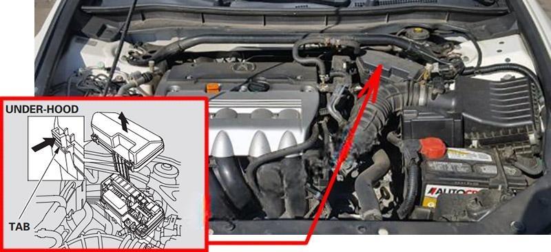
Fuse box diagram (2009-2010)
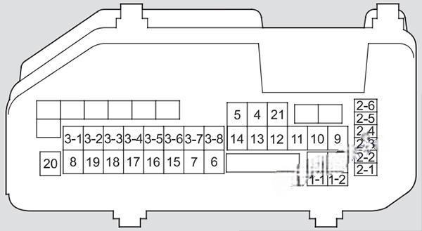
Assignment of fuses in the engine compartment (2009, 2010)
| No. | Amps. | Circuits Protected |
|---|---|---|
| 1-1 | 100 A | Battery (4-cylinder models) |
| 1-1 | 120 A | Battery (6-cylinder models) |
| 1-2 | 40 A | Passenger’s Side Fuse Box |
| 2-1 | 70 A | EPS |
| 2-2 | (40 A) | Passenger’s Side Fuse Box |
| 2-3 | 30 A | ABS/VSA FSR |
| 2-4 | — | Not Used |
| 2-5 | 30 A | ABS/VSA Motor |
| 2-6 | — | Not Used |
| 3-1 | 30 A | Wiper Motor (4-cylinder models) |
| 3-1 | 30 A | Sub Fan Motor (6-cylinder models) |
| 3-2 | — | Not Used (4-cylinder models) |
| 3-2 | 30 A | Wiper Motor (6-cylinder models) |
| 3-3 | 30 A | Main Fan Motor |
| 3-4 | 30 A | Driver’s Side Light Main |
| 3-5 | (60 A) | Driver’s Side Fuse Box |
| 3-6 | 30 A | Passenger’s Side Light Main |
| 3-7 | (40 A) | Driver’s Side Fuse Box |
| 3-8 | 50 A | IG Main |
| 4 | 40 A | Rear Defroster |
| 5 | 20 A | Sub Fan Motor (4-cylinder models) |
| 5 | — | Not Used (6-cylinder models) |
| 6 | — | Not Used |
| 7 | — | Not Used |
| 8 | 40 A | Heater Motor |
| 9 | 15 A | Hazard |
| 10 | 10 A | Horn |
| 11 | — | Not Used |
| 12 | 15 A | Stop |
| 13 | 15 A | IG Coil |
| 14 | 15 A | FI Sub |
| 15 | 10 A | Back Up |
| 16 | 7.5 A | Interior Lights |
| 17 | 15 A | FI Main |
| 18 | 15 A | DBW |
| 19 | — | Not Used (4-cylinder models) |
| 19 | 7.5 A | Back Up FI ECU (6-cylinder models) |
| 20 | 7.5 A | MG Clutch |
| 21 | 7.5 A | Engine Oil Level (4-cylinder models) |
| 21 | 7.5 A | Fan RLY (6-cylinder models) |
Fuse box diagram (2011-2014)
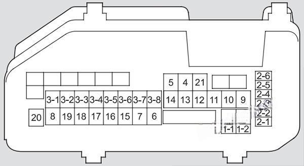
Assignment of fuses in the engine compartment (2011, 2012, 2013, 2014)
| № | Circuit Protected | Amps |
|---|---|---|
| 1 | Battery (4-cylinder models) | 100 A |
| 1 | Battery (6-cylinder models) | 120 A |
| 1 | Passenger’s Side Fuse Box | 40A |
| 2 | EPS | 70 A |
| 2 | Passenger’s Side Fuse Box | (40 A) |
| 2 | ABS/VSA FSR | 30 A |
| 2 | – | – |
| 2 | ABS/VSA Motor | 30 A |
| 2 | – | – |
| 3 | IG | 50 A |
| 3 | Driver’s Side Fuse Box | (40 A) |
| 3 | Passenger’s Side Light Main | 30 A |
| 3 | Driver’s Side Fuse Box | (60 A) |
| 3 | Driver’s Side Light Main | 30 A |
| 3 | Main Fan Motor | 30 A |
| 3 | – (4-cylinder models) | – |
| 3 | Wiper Motor (6-cylinder models) | 30 A |
| 3 | Wiper Motor (4-cylinder models) | 30 A |
| 3 | Sub Fan Motor (6-cylinder models) | 30 A |
| 4 | Rear Defogger | 40 A |
| 5 | Sub Fan Motor (4-cylinder models) | 20 A |
| 5 | – (6-cylinder models) | – |
| 6 | – | – |
| 7 | – | – |
| 8 | Heater Motor | 40 A |
| 9 | Hazard | 15 A |
| 10 | Horn | 10 A |
| 11 | – | – |
| 12 | Stop | 15 A |
| 13 | IG Coil | 15 A |
| 14 | FI Sub | 15 A |
| 15 | Backup | 10A |
| 16 | Interior Lights | 7.5 A |
| 17 | FI Main | 15 A |
| 18 | DBW | 15 A |
| 19 | – (4-cylinder models) | – |
| 19 | Back Up FI ECU (6-cylinder models) | 7.5 A |
| 20 | MG Clutch | 7.5 A |
| 21 | Engine Oil Level (4-cylinder models) | 7.5 A |
| 21 | Fan RLY (6-cylinder models) | 7.5 A |
The driver’s side interior fuse box
Fuse Box Location
It is located under the dashboard on the driver’s side.
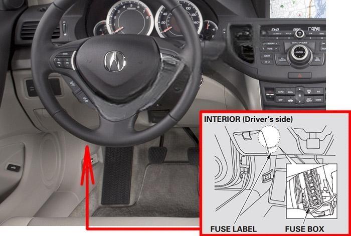
Interior fuse box diagram (driver’s side)
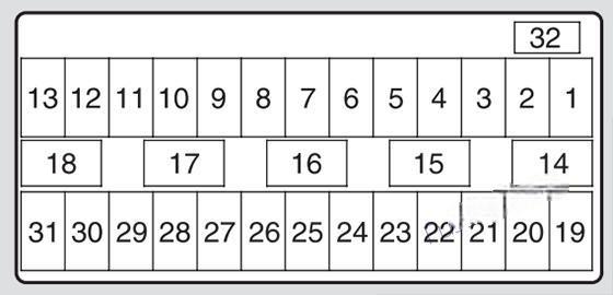
Assignment of fuses in the driver’s side interior fuse box (2009-2014)
| No. | Amps. | Circuits Protected |
|---|---|---|
| 1 | — | Not Used |
| 2 | (7.5 A) | Seat Memory |
| 3 | 15 A | Washer |
| 4 | 10 A | Wiper |
| 5 | 7.5 A | Meter |
| 6 | 7.5 A | ABS/VSA |
| 7 | 15 A | ACG |
| 8 | (7.5 A) | STS (4-cylinder models) |
| 8 | (7.5 A) | Starter DIAG (6-cylinder models) |
| 9 | 20 A | Fuel Pump |
| 10 | (10 A) | VB SOL (If equipped) |
| 11 | 10 A | SRS |
| 12 | 7.5 A | ODS (Occupant Detection System) |
| 13 | (7.5 A) | IG1 (4-cylinder models) |
| 13 | (7.5 A) | STS (6-cylinder models) |
| 14 | — | Not Used |
| 15 | 7.5 A | Daytime Running Lights |
| 16 | 7.5 A | A/C |
| 17 | 7.5 A | Accessory, Key, Lock |
| 18 | 7.5 A | Accessory |
| 19 | (20 A) | Driver’s Power Seat Sliding |
| 20 | (20 A) | Moonroof |
| 21 | (20 A) | Driver’s Power Seat Reclining |
| 22 | 20 A | Rear Driver’s Side Power Window |
| 23 | 20 A | Front Accessory Power Socket |
| 24 | 20 A | Driver’s Power Window |
| 25 | 15 A | Driver’s Side Door Lock |
| 26 | (10 A) | Left Front Fog Light (If equipped) |
| 27 | 10 A | Left Side Small Lights (Exterior) |
| 28 | 10 A | Left Headlight High Beam |
| 29 | 10 A | TPMS |
| 30 | 15 A | Left Headlight Low Beam |
| 31 | — | Not Used |
| 32 | (7.5 A) | Engine Oil Level (If equipped) |
The passenger’s side interior fuse box
Fuse Box Location
The passenger’s side interior fuse box is on the lower passenger’s side panel.
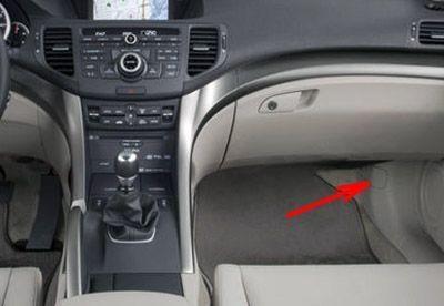
To remove the lid, put your finger in the notch on the lid, and pull it upward slightly, then pull it toward you and take it out of its hinges.
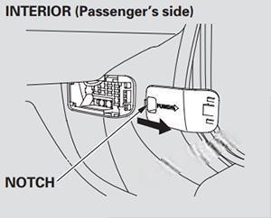
Interior fuse box diagram (passenger’s side)
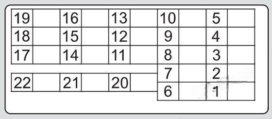
Assignment of fuses in the passenger’s side interior fuse box (2009-2014)
| No. | Amps. | Circuits Protected |
|---|---|---|
| 1 | 10 A | Right Headlight High Beam |
| 2 | 10 A | Right Side Small Lights (Exterior) |
| 3 | (10 A) | Right Front Fog Light (If equipped) |
| 4 | 15 A | Right Headlight Low Beam |
| 5 | — | Not Used |
| 6 | 7.5 A | Interior Lights |
| 7 | — | Not Used |
| 8 | (20 A) | Passenger’s Side Power Seat Reclining |
| 9 | (20 A) | Passenger’s Side Power Seat Sliding |
| 10 | 10 A | Right Side Door Lock |
| 11 | 20 A | Rear Passenger’s Side Power Window |
| 12 | 20 A | Console Accessory Power Socket |
| 13 | 20 A | Front Passenger’s Power Window |
| 14 | — | Not Used |
| 15 | (20 A) | Premium AMP (If equipped) |
| 16 | — | Not Used |
| 17 | — | Not Used |
| 18 | — | Not Used |
| 19 | (20 A) | Seat Heater |
| 20 | — | Not Used |
| 21 | — | Not Used |
| 22 | — | Not Used |
