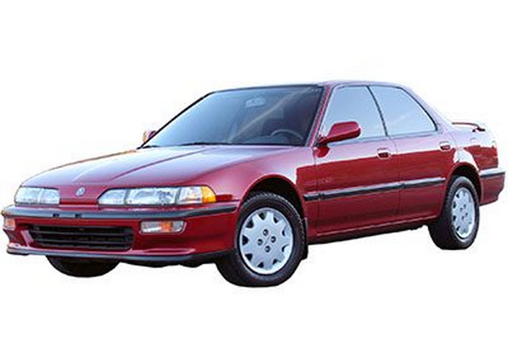
In this article we look at the second-generation Acura Integra, produced from 1990 to 1993. Here you will find the Acura Integra 1990, 1991, 1992 and 1993 fuse box diagrams, get information on the location of the fuse boxes inside the car and learn about the assignment of each fuse (fuse layout) and relay.
Passenger Compartment Fuse Box
Fuses/Relays Location
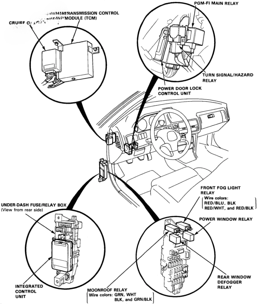
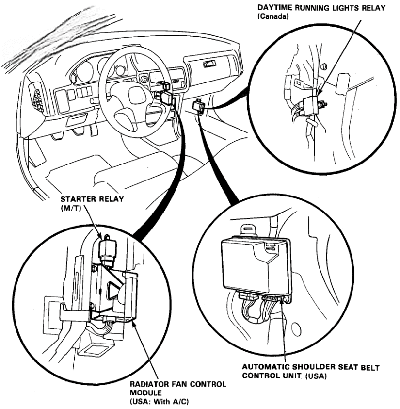
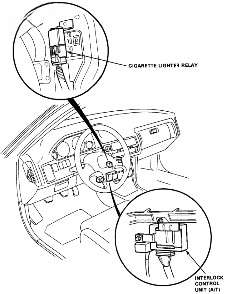
Fuse Box Diagram
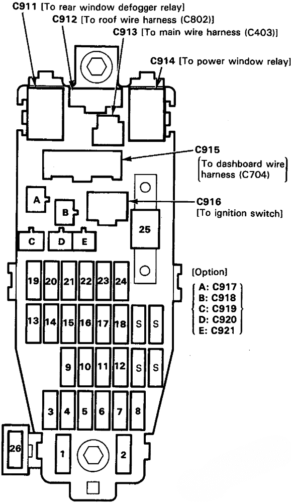
Assignment of the fuses in the passenger compartment
| № | Amps | Description |
|---|---|---|
| 1 | 10A | Turn signal lights/relay Back-up lights |
| 2 | 20A | Right front power window motor |
| 3 | 10A | Right headlight (Low beam) |
| 4 | 10A | Left headlight (Low beam) Front fog light relay |
| 5 | 20A | Power door lock control unit |
| 6 | 20A | Left rear power window motor |
| 7 | 20A | Driver’s power window master switch/motor |
| 8 | 20A | Right rear power window motor |
| 9 | 10A | Right headlight (High beam) High beam indicator light |
| 10 | 10A | Left headlight (High beam) |
| 11 | 15A | Integrated control unit Heater control panel lights A/C switch light Front parking lights Dash lights brightness controller Dash lights Glove box light Lightslin dim modelfor clock, A/T gear position indicator and cruise control indicator Taillights/rear side marker lights License plate lights Trailer |
| 12 | 15A | Radiator fan motor (With A/C) |
| 13 | – | – |
| 14 | 15A | Integrated control unit Clock (+B) Cigarette lighter Stereo radio/cassette player (+B) Ceiling light Power antenna motor Trunk/Cargo area light Front map light Trailer |
| 15 | 20A | Canada: Moonroof motor |
| 16 | 20A | Integrated control unit (Combined operation wiper/washer) (Canada) Power window relay Windshield wiper motor Washer motors Rear window wiper motor Moonroof relay |
| 17 | 7.5A | Rear window defoggar switch indicator light Rear window defogger relay Power mirrors A/C compressor clutch relay Condenser fan relay (Canada) A/C switch indicator light Heater control panel Heater mode control motor Recirculation control motor ABS control unit ABS motor relay ABS front fail-safe relay ABS rear fail-safe relay |
| 18 | 7.5A | Starter signal ECM PGM-FI check circuit |
| 19 | 10A | Front fog lights |
| 20 | 15A | Radiator fan control module (With A/C) Condenser fan motor A/C compressor clutch |
| 21 | 15A | Radiator fan motor (Without A/C) Radiator fan relay (With A/C) Radiator fan control module (With A/C) |
| 22 | 10A | Stereo radio/cassette player (ACC) Cigarette lighter relay |
| 23 | 7.5A | Integrated control unit (IG1) Gauge and warning lights Cruise control indicator A/T gear position indicator Shift lock solenoid Clock Automatic shoulder seat belt control unit (US) |
| 24 | 15A | PGM-FI main relay and fuel pump EGR control solenoid valve Evaporatiye emission (EVAP) purge control solenoid valve Fuel pressure regulator cut-off solenoid valve Voltage regulator (IG1) Radiator fan control module (US With A/C) Cruise control unit |
| 25 | 40A | IGNITION SWITCH (BAT -B) Blower motor Ignition coil and Ignition control module (ICM) |
| 26 | 7.5A | Canada: DRL RELAY |
| S | Spare fuses |
Engine Compartment Fuse Box
Fuses/Relays Location
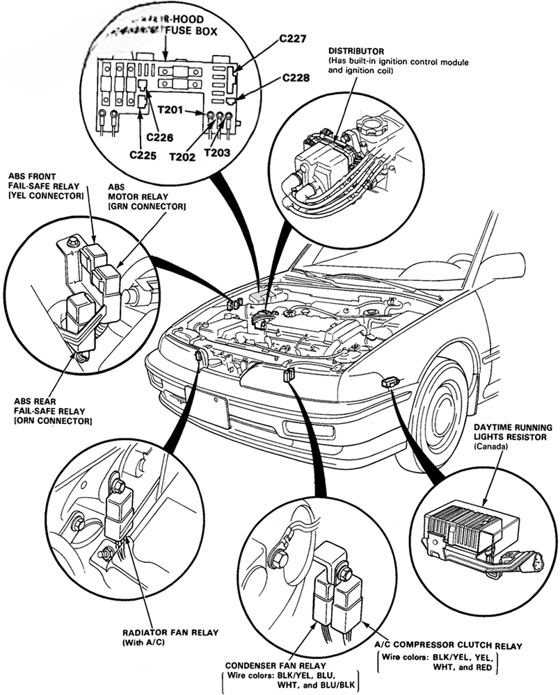
Fuse Box Diagram
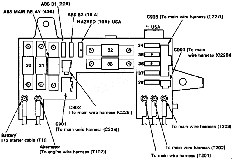
Assignment of the fuses in the engine compartment
| № | Amps | Description |
|---|---|---|
| ABS MAIN | 40A | ABS motor |
| ABS B1 | 20A | ABS control unit |
| ABS B2 | 15A | ABS control unit |
| HAZARD | 10A | Hazard warning light Turn signal/hazard relay |
| 30 | 80A | All |
| 31 | 30A | Rear window defogger |
| 32 | 50A | IGNITION SWITCH: Fuses №1, 16, 17, 18, 21, 22, 23, 24, 25, 26 Starter solenoid Starter relay |
| 33 | 50A | LIGHTING CIRCUIT: Fuses №3, 4, 9, 10, 11, 14, 19 |
| 34 | 7.5A / 10A | US (7.5A): Integrated control unit (Key-in beeper circuit) ECM Transmission control module (TCM) Automatic shoulder seat belt control unit Canada (10A): Hazard warning lights Turn signal/hazard relay ECM Transmission control module (TCM) Integrated control unit |
| 35 | 30A | US: Automatic shoulder seat belt control unit |
| 36 | 30A | US: Automatic shoulder seat belt control unit |
| 37 | 20A | Brake lights, Brake signal Horns Key interlock solenoid (A/T) |
| 38 | 10A | PGM-FI main relay (+B) |
